\n
## Diagram: System Block Representation with Transformation
### Overview
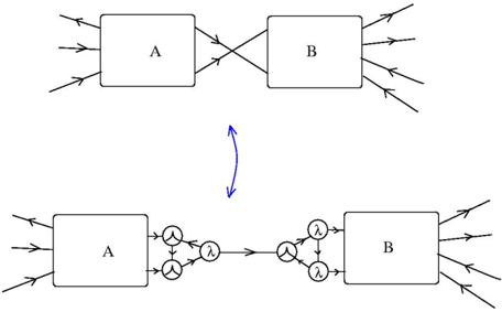
The image presents a diagram illustrating a system transformation between two blocks, labeled 'A' and 'B'. The top portion shows a direct, crossed connection between the blocks, while the bottom portion depicts a transformation of this connection using intermediate elements represented by circles with the symbol 'λ' inside. A curved blue arrow between the two sections indicates a transformation or mapping process.
### Components/Axes
The diagram consists of:
* **Block A:** A rectangular block labeled "A". It has multiple input arrows on the left and output arrows that connect to Block B in the top diagram.
* **Block B:** A rectangular block labeled "B". It has multiple input arrows from Block A in the top diagram and multiple output arrows on the right.
* **Input Arrows:** Multiple arrows pointing towards Block A, representing inputs.
* **Output Arrows:** Multiple arrows originating from Block B, representing outputs.
* **Crossed Connections:** Lines connecting the outputs of Block A to the inputs of Block B, crossing each other in the top diagram.
* **Lambda (λ) Elements:** Circles containing the symbol 'λ', positioned between Block A and Block B in the bottom diagram. These are connected to both Block A and Block B.
* **Transformation Arrow:** A curved blue arrow pointing downwards, indicating a transformation from the top diagram to the bottom diagram.
### Detailed Analysis or Content Details
The top diagram shows a direct connection between Block A and Block B. The connections are not explicitly defined in terms of quantity or type, but there are at least two crossing lines.
The bottom diagram shows a more complex connection. Block A has multiple outputs that split into three paths, each leading to a 'λ' element. Each 'λ' element then connects to Block B. Block B also has multiple inputs from the 'λ' elements. The number of 'λ' elements appears to be three. The 'λ' symbol suggests a transformation or function being applied to the signal or data.
### Key Observations
* The transformation arrow suggests that the bottom diagram represents a decomposition or expansion of the connections shown in the top diagram.
* The 'λ' elements likely represent some form of processing or transformation applied to the signals passing between Block A and Block B.
* The diagram does not provide any quantitative information about the signals or the transformations. It is a conceptual representation of a system.
### Interpretation
The diagram illustrates a system where Block A and Block B are interconnected. The top diagram shows a simplified, direct connection. The bottom diagram demonstrates a more detailed representation of this connection, where the signal flow is mediated by 'λ' elements. These 'λ' elements likely represent functions or transformations applied to the signal. The curved arrow indicates that the bottom diagram is a more refined or expanded view of the relationship between A and B.
This could represent a system where Block A generates signals, Block B processes them, and the 'λ' elements represent intermediate processing steps or parameters that influence the signal flow. The use of 'λ' suggests a mathematical or functional transformation. The diagram is abstract and does not specify the nature of the blocks or the transformations, but it provides a conceptual framework for understanding the system's architecture. The diagram is a visual representation of a system's architecture, focusing on the flow of information or signals between components. It doesn't provide specific data or values, but rather a qualitative depiction of the system's structure and relationships.