## Diagram: LOC Pruning Examples
### Overview
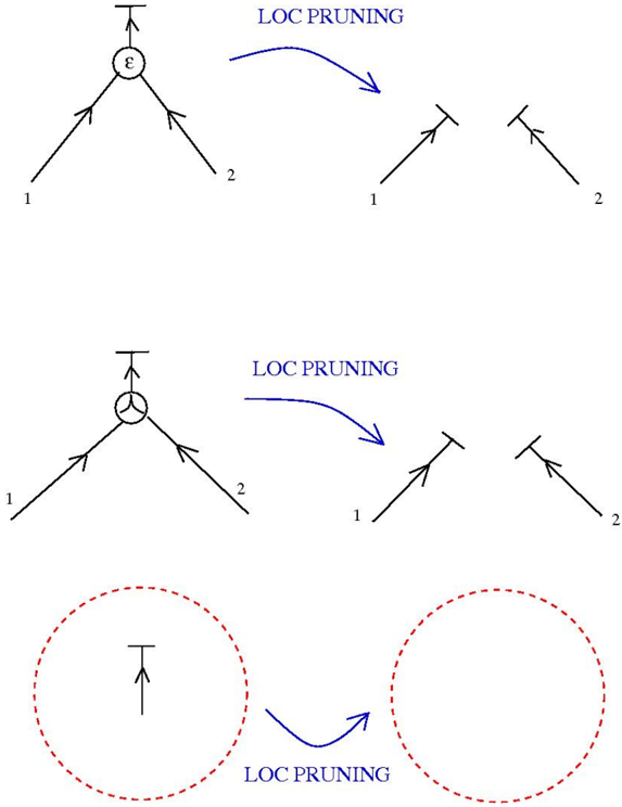
The image illustrates the concept of "LOC PRUNING" through three separate examples. Each example shows an initial state with connected components and a subsequent state after pruning, indicated by a curved arrow labeled "LOC PRUNING".
### Components/Axes
* **Nodes:** Represented by circles, some containing symbols (ε, a circle with a cross inside, and a line with a perpendicular line above it).
* **Edges:** Represented by lines with arrowheads, indicating direction.
* **Labels:** Numerical labels "1" and "2" are associated with the edges.
* **Text Labels:** "LOC PRUNING" is written in blue text with an arrow indicating the transformation.
### Detailed Analysis
**Example 1 (Top):**
* Initial state: A node containing the symbol "ε" connects to two edges, labeled "1" and "2".
* Pruning: "LOC PRUNING" transforms this into two separate edges, labeled "1" and "2", each with a short perpendicular line above the arrow.
**Example 2 (Middle):**
* Initial state: A node containing a circle with a cross inside connects to two edges, labeled "1" and "2".
* Pruning: "LOC PRUNING" transforms this into two separate edges, labeled "1" and "2", each with a short perpendicular line above the arrow.
**Example 3 (Bottom):**
* Initial state: A node represented by a line with a perpendicular line above it, enclosed in a dashed red circle.
* Pruning: "LOC PRUNING" transforms this into an empty dashed red circle.
### Key Observations
* "LOC PRUNING" appears to disconnect nodes and edges.
* The specific symbol within the node in the initial state seems to be irrelevant to the pruning process.
* The dashed red circles in the third example suggest a region or scope being pruned.
### Interpretation
The diagram illustrates a process called "LOC PRUNING," which involves removing connections or elements from a network or system. The examples show different initial configurations being transformed into disconnected components or empty regions. The "LOC PRUNING" label suggests that this process is localized, potentially focusing on specific areas or components within a larger system. The red dashed circles may indicate the scope or boundary of the pruning operation. The diagram does not provide specific details about the criteria or mechanisms for pruning, but it visually represents the outcome of the process.