\n
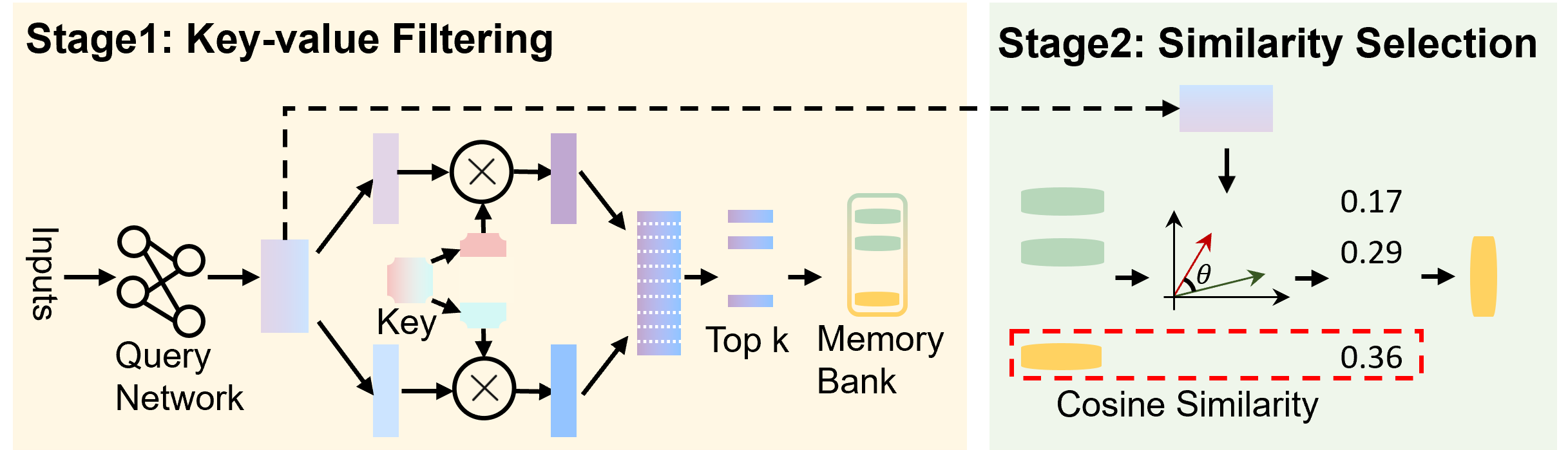
## Diagram: Key-Value Filtering and Similarity Selection
### Overview
This diagram illustrates a two-stage process: Key-value Filtering and Similarity Selection. The diagram depicts a flow of information from "Inputs" through a "Query Network", followed by filtering using "Key" vectors, selection of "Top k" elements from a "Memory Bank", and finally, a "Similarity Selection" stage based on "Cosine Similarity". The diagram uses arrows to indicate the direction of information flow and circular elements with 'X' symbols to represent operations.
### Components/Axes
The diagram is divided into two main stages, visually separated by a dashed gray line and labeled with light yellow background.
* **Stage 1: Key-value Filtering:** Contains "Inputs", "Query Network", "Key", "Top k", and "Memory Bank".
* **Stage 2: Similarity Selection:** Contains vectors with angle θ, and "Cosine Similarity" values.
* **Inputs:** Represented by a cluster of connected circles.
* **Query Network:** A light-blue, rounded rectangle.
* **Key:** Labelled below two circular elements with 'X' symbols.
* **Top k:** A stack of purple rectangles.
* **Memory Bank:** A stack of yellow cylinders.
* **Cosine Similarity:** A red dashed rectangle containing numerical values.
* **θ:** An angle symbol indicating the angle between two vectors.
### Detailed Analysis or Content Details
**Stage 1: Key-value Filtering**
1. **Inputs:** A set of interconnected circles, suggesting multiple input features.
2. **Query Network:** The inputs feed into a "Query Network".
3. **Key Generation:** The output of the Query Network is used to generate "Key" vectors. Two circular elements with 'X' symbols are shown, indicating a multiplication or comparison operation.
4. **Filtering:** The "Key" vectors are used to filter the "Memory Bank", selecting the "Top k" elements. The Memory Bank is represented as a stack of yellow cylinders. The "Top k" elements are represented as a stack of purple rectangles.
**Stage 2: Similarity Selection**
1. **Vector Representation:** Two vectors are shown, with an angle θ between them.
2. **Cosine Similarity Calculation:** The diagram displays three "Cosine Similarity" values: 0.17, 0.29, and 0.36. These values are associated with the vectors and are enclosed in a red dashed rectangle. The values are positioned to the right of the vectors.
### Key Observations
* The diagram illustrates a retrieval process where inputs are transformed into queries, used to filter a memory bank, and then ranked based on similarity.
* The "Key" vectors appear to be used for filtering the "Memory Bank".
* The "Cosine Similarity" values suggest a ranking or scoring mechanism based on the angle between vectors.
* The values 0.17, 0.29, and 0.36 represent the cosine similarity scores between the query vector and the retrieved vectors from the memory bank.
### Interpretation
The diagram depicts a key-value memory network or a similar retrieval-augmented generation architecture. The first stage filters the memory bank based on the similarity between the query and the keys associated with the memory entries. The second stage then selects the most similar entries based on cosine similarity. The increasing cosine similarity values (0.17, 0.29, 0.36) suggest that the selected vectors are becoming more aligned with the query vector, indicating a higher degree of relevance. This process is commonly used in tasks like information retrieval, question answering, and recommendation systems. The diagram provides a high-level overview of the process without specifying the exact implementation details of the query network or the memory bank. The use of cosine similarity implies that the vectors are normalized, and the angle between them is used to measure their similarity.