## Diagram: Communication Policy Network
### Overview
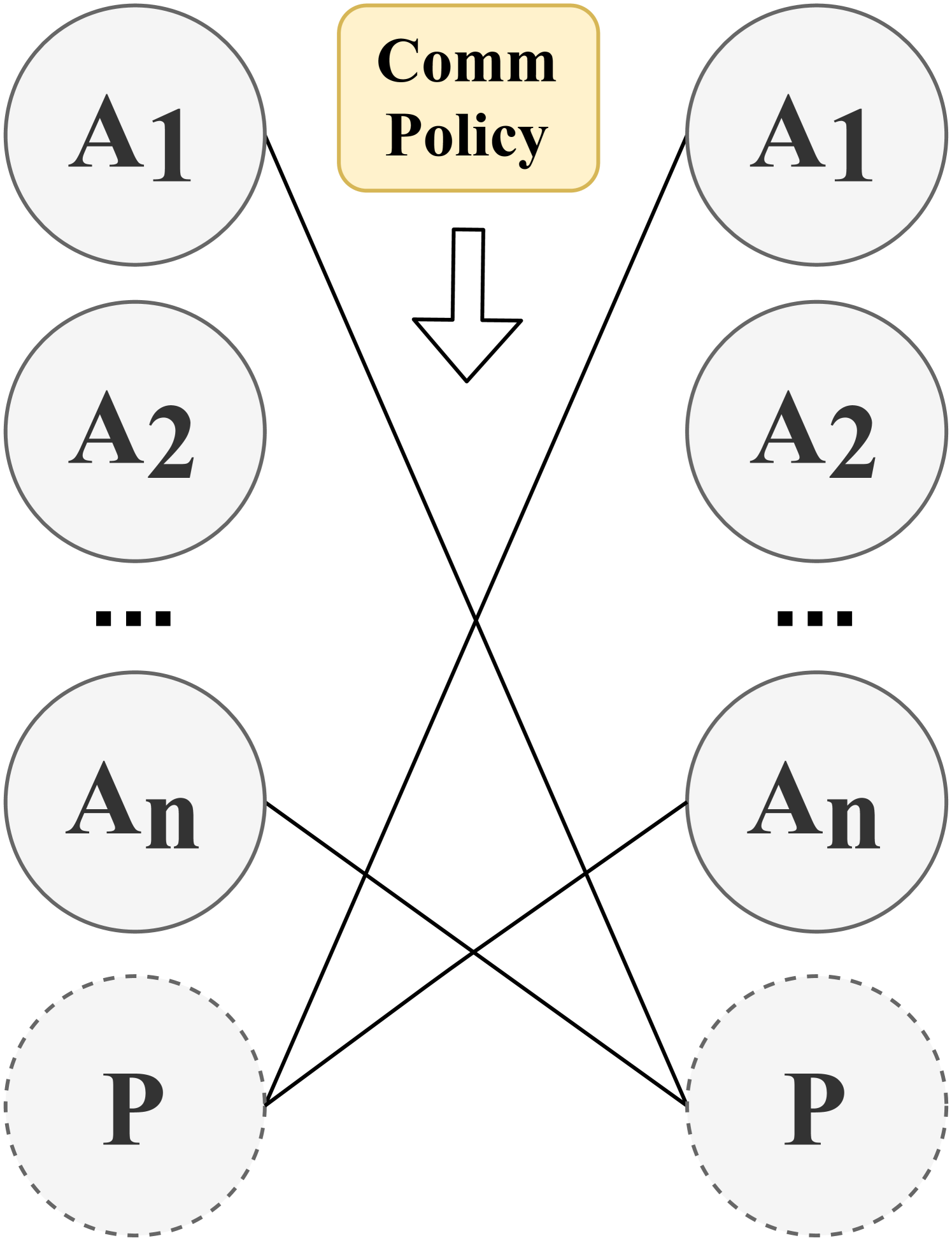
The diagram illustrates a communication policy network involving multiple agents (A1, A2, ..., An), a central "Comm Policy" component, and a principal (P). Arrows indicate directional relationships, while dashed lines suggest indirect or secondary connections.
### Components/Axes
- **Nodes**:
- **Agents**: Labeled A1, A2, ..., An (arranged in two vertical columns on the left and right).
- **Central Policy**: A yellow box labeled "Comm Policy" at the top center.
- **Principal**: Two dashed circles labeled P at the bottom left and right.
- **Connections**:
- Solid arrows from each agent (A1–An) to the "Comm Policy" box.
- Solid arrows from "Comm Policy" to both P nodes.
- Dashed bidirectional lines connecting the two P nodes.
### Detailed Analysis
- **Agent-to-Policy Flow**: Each agent (A1–An) directly influences the "Comm Policy" via solid arrows, indicating a one-way communication or dependency.
- **Policy-to-Principal Flow**: The "Comm Policy" box directs output to both P nodes, suggesting the policy governs or impacts the principal(s).
- **Principal Interconnection**: Dashed lines between the two P nodes imply a mutual relationship (e.g., collaboration, shared responsibility, or feedback loop).
### Key Observations
1. **Hierarchical Structure**: Agents → Policy → Principal(s) forms a top-down hierarchy.
2. **Symmetry**: The diagram is mirrored left-right, with identical agent and principal configurations.
3. **Dashed Lines**: The bidirectional dashed lines between P nodes suggest a non-hierarchical or reciprocal relationship, contrasting with the solid directional arrows elsewhere.
### Interpretation
This diagram likely represents a governance or decision-making framework where:
- **Agents** (A1–An) contribute inputs to a centralized **Communication Policy**.
- The **Policy** acts as a mediator, translating agent inputs into actions or decisions for the **Principal(s)** (P).
- The dashed lines between P nodes may indicate:
- Shared oversight (e.g., co-governance).
- Redundancy (e.g., backup systems).
- Feedback mechanisms (e.g., mutual adjustment).
The absence of feedback loops from P to agents or policy suggests a unidirectional flow of influence, emphasizing top-down control. The symmetry implies balanced roles for agents and principals, while the dashed lines introduce ambiguity about the nature of principal interactions.