## Diagram: Communication Policy
### Overview
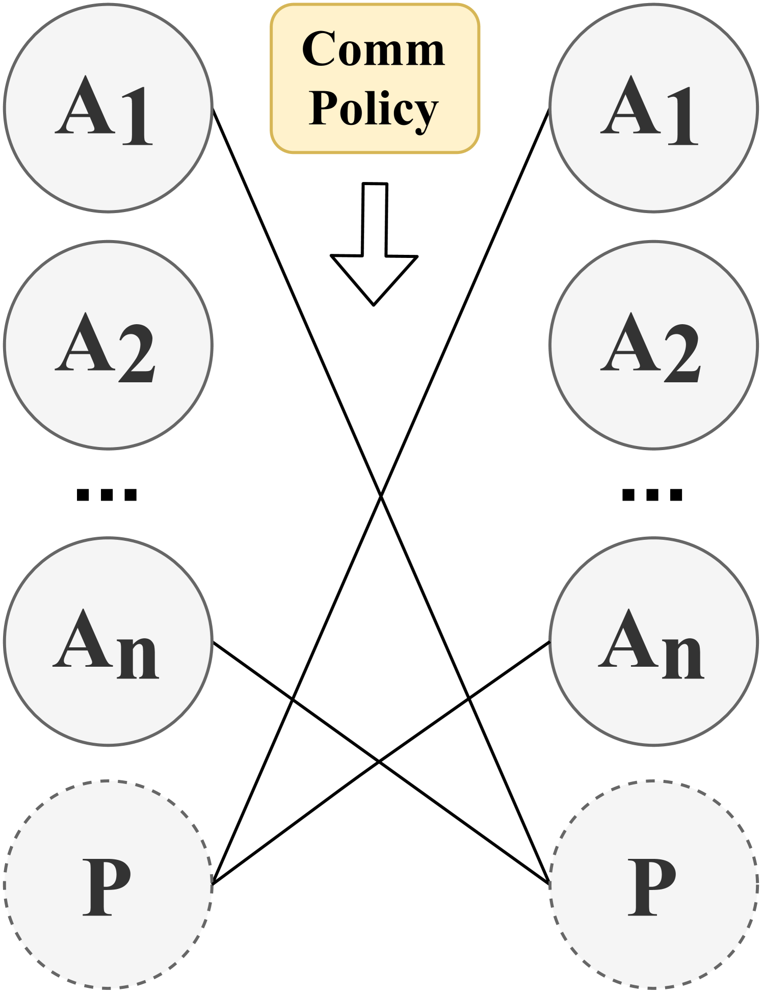
The image is a diagram illustrating a communication policy between a central "Comm Policy" node and two sets of nodes labeled "A1" to "An" and "P". The diagram shows connections between the "A" nodes on the left and the "P" nodes on the right, mediated by the "Comm Policy" at the top.
### Components/Axes
* **Nodes:**
* "Comm Policy" - A yellow rounded rectangle at the top-center.
* "A1", "A2", ..., "An" - A series of nodes on the left side, represented as circles with solid gray outlines.
* "A1", "A2", ..., "An" - A series of nodes on the right side, represented as circles with solid gray outlines.
* "P" - Two nodes at the bottom, represented as circles with dashed gray outlines.
* **Connections:** Black lines connecting nodes.
* **Flow Direction:** An arrow pointing downwards from the "Comm Policy" node.
### Detailed Analysis
* **Comm Policy:** Located at the top-center of the diagram. The text inside the yellow rounded rectangle reads "Comm Policy".
* **Left Side Nodes:**
* "A1" is the top-most node.
* "A2" is below "A1".
* "..." indicates a continuation of the series.
* "An" is the last node in the series.
* "P" is the bottom-most node, with a dashed outline.
* **Right Side Nodes:**
* "A1" is the top-most node.
* "A2" is below "A1".
* "..." indicates a continuation of the series.
* "An" is the last node in the series.
* "P" is the bottom-most node, with a dashed outline.
* **Connections:**
* "A1" on the left is connected to "An" and "P" on the right.
* "An" on the left is connected to "A1" and "P" on the right.
* **Flow:** The arrow indicates a downward flow from the "Comm Policy" towards the nodes.
### Key Observations
* The "Comm Policy" node appears to be a central point of control or influence.
* The "A" nodes are arranged in a series, suggesting a sequence or hierarchy.
* The "P" nodes have dashed outlines, possibly indicating a different status or role compared to the "A" nodes.
* The connections between the left and right sides are cross-linked, indicating a complex communication pattern.
### Interpretation
The diagram illustrates a communication policy where the "Comm Policy" node influences or controls the interactions between two sets of nodes. The "A" nodes likely represent agents or entities, while the "P" nodes could represent processes or resources. The cross-linked connections suggest a many-to-many communication pattern, where each "A" node on one side can interact with multiple nodes on the other side. The dashed outline of the "P" nodes might indicate that they are passive or dependent entities in the communication process. The downward arrow from "Comm Policy" suggests that the policy is enforced or applied to the interactions between the "A" and "P" nodes.