\n
## Diagram: Binaural Waveform Generation Pipeline
### Overview
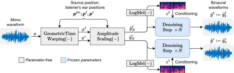
This diagram illustrates a pipeline for generating binaural waveforms from a monaural waveform. The process involves geometric time warping, amplitude scaling, LogMel conditioning, and denoising steps. The diagram highlights which components are parameter-free versus those with frozen parameters.
### Components/Axes
The diagram consists of the following components, arranged in a sequential flow from left to right:
* **Mono waveform (x):** The input signal.
* **Geometric Time Warping (-):** A processing step that transforms the input waveform (x) into x'.
* **Amplitude Scaling (-):** A processing step that transforms the warped waveform (x') into ŷ<sub>N</sub>.
* **Source position; listener's ear positions:** Labeled as p<sup>src</sup>, p<sup>L</sup>, p<sup>R</sup>. These are inputs to the Amplitude Scaling step.
* **LogMel (-):** A transformation applied to the output of Amplitude Scaling (ŷ<sub>N</sub>) to produce c'.
* **Conditioning:** The LogMel output (c') is used for conditioning.
* **Denoising Step x N:** A denoising process repeated N times.
* **Binaural waveforms (y<sup>L</sup>, y<sup>R</sup>):** The final output, representing the left and right ear signals.
The diagram also includes a legend:
* **White boxes with white borders:** Parameter-free components.
* **Light blue boxes with light blue borders:** Frozen parameter components.
### Detailed Analysis / Content Details
The pipeline begins with a monaural waveform, denoted as 'x'. This waveform is fed into a 'Geometric Time Warping' block, resulting in a transformed waveform 'x''. The 'x'' waveform then enters an 'Amplitude Scaling' block, which takes the 'Source position; listener's ear positions' (p<sup>src</sup>, p<sup>L</sup>, p<sup>R</sup>) as input, and outputs ŷ<sub>N</sub>. The ŷ<sub>N</sub> signal is then processed by a 'LogMel' transformation, resulting in 'c''. This 'c'' signal is used for 'Conditioning'.
The conditioned signal then feeds into two parallel 'Denoising Step x N' blocks. Each denoising step is conditioned by a 'LogMel' transformation of ŷ<sub>N</sub> and 'Conditioning'. The outputs of these denoising steps are the binaural waveforms 'y<sup>L</sup>' (left ear) and 'y<sup>R</sup>' (right ear).
The 'Geometric Time Warping' and 'Denoising Step x N' blocks are indicated as parameter-free (white boxes). The 'Amplitude Scaling' and 'LogMel' blocks are indicated as having frozen parameters (light blue boxes).
### Key Observations
The diagram shows a clear flow of information from a monaural signal to binaural signals. The use of parallel denoising steps suggests a potential for redundancy or different processing paths for the left and right channels. The distinction between parameter-free and frozen parameter components is important for understanding the flexibility and adaptability of the pipeline.
### Interpretation
This diagram represents a signal processing pipeline designed to create a 3D audio experience from a single audio source. The geometric time warping and amplitude scaling likely simulate the effects of sound arriving at each ear at slightly different times and with different intensities, due to the head and ear shape. The LogMel transformation is a common technique for representing audio signals in a way that is perceptually relevant to humans. The denoising steps are crucial for removing unwanted noise and artifacts, resulting in a clean and realistic binaural signal. The separation of parameter-free and frozen parameter components suggests a design that allows for customization of the denoising process while maintaining a stable and predictable base for the time warping and amplitude scaling. The 'N' in 'Denoising Step x N' indicates that the denoising process is iterative, potentially improving the quality of the binaural signal with each step. The diagram suggests a sophisticated approach to binaural audio rendering, leveraging signal processing techniques to create a convincing spatial audio experience.