## Memristor Diagram: Volatile vs. Non-Volatile
### Overview
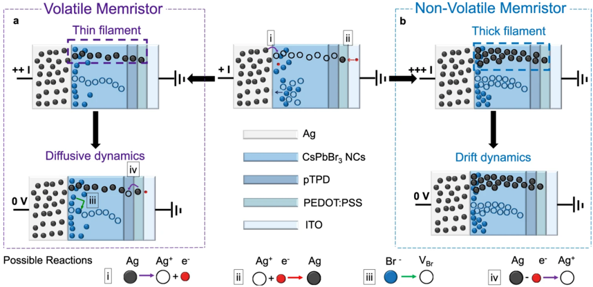
The image presents a diagram comparing the operational dynamics of volatile and non-volatile memristors. It illustrates the movement of ions and the formation/dissolution of filaments within the memristor structure under different voltage conditions. The diagram is divided into two main sections, 'a' for the volatile memristor and 'b' for the non-volatile memristor. Each section shows the memristor's state under an applied voltage and after the voltage is removed.
### Components/Axes
The diagram includes the following components:
* **Title (Top-Left)**: "Volatile Memristor" (enclosed in a dashed purple box)
* **Title (Top-Right)**: "Non-Volatile Memristor" (enclosed in a dashed light blue box)
* **Memristor Structure**: Each memristor consists of layers labeled as:
* Ag (Silver)
* CsPbBr3 NCs (Cesium Lead Bromide Nanocrystals)
* pTPD
* PEDOT:PSS
* ITO (Indium Tin Oxide)
* **Voltage Indicators**: "+ + I", "0 V", "+ + + I"
* **Filament Labels**: "Thin filament" (purple dashed box, volatile), "Thick filament" (light blue dashed box, non-volatile)
* **Dynamics Labels**: "Diffusive dynamics" (volatile), "Drift dynamics" (non-volatile)
* **Reaction Legend (Bottom)**:
* i: Ag -> Ag+ + e- (Silver atom becomes a silver ion and an electron)
* ii: Ag+ + e- -> Ag (Silver ion and an electron become a silver atom)
* iii: Br- -> VBr (Bromide ion becomes a Bromine vacancy)
* iv: Ag -> e- + Ag+ (Silver atom becomes an electron and a silver ion)
### Detailed Analysis or Content Details
**Volatile Memristor (a):**
1. **Initial State (+ + I):** A "Thin filament" (purple dashed box) of silver (Ag) atoms and ions (Ag+) forms between the Ag and ITO layers through the CsPbBr3 NCs layer.
2. **Diffusive Dynamics (0 V):** When the voltage is removed (0 V), the filament dissolves due to diffusion. The Ag atoms and ions disperse back into the CsPbBr3 NCs layer.
**Non-Volatile Memristor (b):**
1. **Initial State (+ + + I):** A "Thick filament" (light blue dashed box) of Ag atoms and ions forms between the Ag and ITO layers.
2. **Drift Dynamics (0 V):** When the voltage is removed (0 V), the filament remains intact due to drift dynamics. The Ag atoms and ions do not readily disperse.
**Reaction Details:**
* **Reaction i:** A solid gray circle (Ag) with a purple arrow pointing to an open circle (Ag+) and a small red circle (e-).
* **Reaction ii:** An open circle (Ag+) and a small red circle (e-) with a red arrow pointing to a solid gray circle (Ag).
* **Reaction iii:** A solid dark blue circle (Br-) with a green arrow pointing to an open circle (VBr).
* **Reaction iv:** A solid gray circle (Ag) with a purple arrow pointing to a small red circle (e-) and an open circle (Ag+).
### Key Observations
* The key difference between volatile and non-volatile memristors lies in the stability of the filament after the voltage is removed.
* Volatile memristors exhibit filament dissolution due to diffusion, while non-volatile memristors maintain the filament due to drift dynamics.
* The thickness of the filament appears to influence the stability.
### Interpretation
The diagram illustrates the fundamental mechanisms behind volatile and non-volatile memristor behavior. The volatile memristor's "thin filament" is unstable without an applied voltage, leading to its dissolution and a return to a high-resistance state. This behavior is attributed to the diffusion of silver ions. In contrast, the non-volatile memristor's "thick filament" remains stable even without an applied voltage, maintaining a low-resistance state. This stability is due to drift dynamics, which prevent the silver ions from dispersing. The reactions listed at the bottom explain the chemical processes involved in the formation and dissolution of the silver filament, including the oxidation and reduction of silver and the formation of bromine vacancies. The diagram highlights the importance of controlling ion mobility and filament stability in memristor design for different applications.