\n
## Diagram: Memory Localization Schemes
### Overview
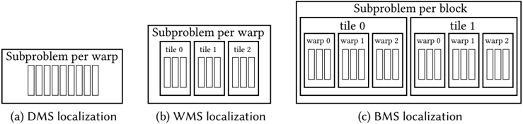
The image presents a comparative diagram illustrating three different memory localization schemes: DMS (Data-level Multithreading Synchronization), WMS (Warp-level Multithreading Synchronization), and BMS (Block-level Multithreading Synchronization). Each scheme is represented by a rectangular box containing vertical bars, visually representing subproblems, and labeled to indicate how these subproblems are organized and mapped to memory.
### Components/Axes
The diagram consists of three labeled sections:
* **(a) DMS localization:** Labeled "Subproblem per warp" above a rectangular box containing approximately 8-10 vertical bars.
* **(b) WMS localization:** Labeled "Subproblem per warp" above a rectangular box divided into three smaller boxes labeled "tile 0", "tile 1", and "tile 2". Each tile contains approximately 3-4 vertical bars.
* **(c) BMS localization:** Labeled "Subproblem per block" above a larger rectangular box divided into two larger boxes labeled "tile 0" and "tile 1". Each tile is further divided into three smaller boxes labeled "warp 0", "warp 1", and "warp 2". Each warp contains approximately 3-4 vertical bars.
### Detailed Analysis or Content Details
* **DMS Localization (a):** The scheme appears to assign one subproblem per warp. The number of subproblems (represented by the vertical bars) is approximately 8-10.
* **WMS Localization (b):** This scheme divides the subproblems into tiles. There are three tiles (0, 1, and 2), each containing approximately 3-4 subproblems. The overall number of subproblems is approximately 9-12.
* **BMS Localization (c):** This scheme divides the subproblems into tiles (0 and 1) and further into warps (0, 1, and 2) within each tile. Each warp contains approximately 3-4 subproblems. The total number of subproblems is approximately 18-24.
### Key Observations
The primary difference between the schemes lies in the granularity of subproblem allocation. DMS allocates at the warp level, WMS at the tile level within a warp, and BMS at the warp level within a tile. The number of subproblems increases from DMS to WMS to BMS.
### Interpretation
The diagram illustrates a progression in memory localization strategies. DMS appears to be the simplest, allocating a single warp to each subproblem. WMS introduces tiling to potentially improve memory access patterns by grouping subproblems. BMS further refines this by adding a warp-level division within each tile, potentially enabling finer-grained control over memory access and parallelism. The increasing number of subproblems in BMS suggests a greater degree of parallelism and potentially higher performance, but also increased complexity in managing the memory allocation. The diagram suggests a trade-off between simplicity, memory access efficiency, and parallelism. The choice of scheme would depend on the specific application and hardware architecture.