## Diagram: Comparison of GPU Localization Strategies
### Overview
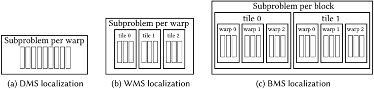
The image displays three schematic diagrams, labeled (a), (b), and (c), illustrating different hierarchical strategies for mapping computational subproblems to GPU execution units. The diagrams progress from a flat structure to increasingly nested and hierarchical structures, representing different levels of localization (DMS, WMS, BMS).
### Components/Axes
The image contains three distinct diagrams arranged horizontally. Each diagram is a box containing nested rectangular elements and text labels. There are no traditional chart axes or legends. The primary textual elements are the titles below each diagram and the labels within the nested boxes.
**Diagram (a):**
* **Title (below):** "(a) DMS localization"
* **Main Box Label (top):** "Subproblem per warp"
* **Internal Elements:** A single row of 8 identical, narrow vertical rectangles (representing warps or threads).
**Diagram (b):**
* **Title (below):** "(b) WMS localization"
* **Main Box Label (top):** "Subproblem per warp"
* **Internal Structure:** Three larger boxes labeled "tile 0", "tile 1", and "tile 2". Each tile box contains a row of 4 identical, narrow vertical rectangles (warps/threads).
**Diagram (c):**
* **Title (below):** "(c) BMS localization"
* **Main Box Label (top):** "Subproblem per block"
* **Internal Structure:** Two large boxes labeled "tile 0" and "tile 1". Each tile box contains three smaller boxes labeled "warp 0", "warp 1", and "warp 2". Each warp box contains a row of 4 identical, narrow vertical rectangles (threads).
### Detailed Analysis
The diagrams depict a clear hierarchical decomposition:
1. **DMS (a):** The most granular view. A single "Subproblem per warp" is shown, containing 8 execution units (warps/threads) in a flat, ungrouped structure.
2. **WMS (b):** Introduces an intermediate grouping level. The "Subproblem per warp" is now divided into 3 "tiles". Each tile contains 4 execution units. The total number of execution units is 12 (3 tiles * 4 units).
3. **BMS (c):** The highest level of grouping. The main label changes to "Subproblem per block". This block is divided into 2 "tiles". Each tile is further subdivided into 3 "warps". Each warp contains 4 execution units. The total number of execution units is 24 (2 tiles * 3 warps * 4 units).
**Spatial Grounding:** The labels are consistently placed at the top of their respective containing boxes. The nesting is visually clear: in (c), the "warp" boxes are fully contained within the "tile" boxes, which are fully contained within the main "Subproblem per block" box.
### Key Observations
* **Increasing Hierarchy:** The progression from (a) to (c) shows an increase in structural hierarchy (Warp -> Tile -> Block).
* **Changing Granularity:** The fundamental unit of work assignment changes from "per warp" in (a) and (b) to "per block" in (c).
* **Varying Group Sizes:** The number of elements at each level changes:
* Tiles per subproblem: 0 in (a), 3 in (b), 2 in (c).
* Warps per tile: 1 (implicit) in (a), 1 (implicit) in (b), 3 in (c).
* Threads per warp: 8 in (a), 4 in (b), 4 in (c).
* **Visual Consistency:** The narrow vertical rectangles representing the finest-grained execution units (likely threads) are visually identical across all three diagrams.
### Interpretation
This diagram illustrates three different strategies for **localizing data or work** within a GPU's execution hierarchy to optimize performance, likely for a parallel computing kernel.
* **DMS (Distributed Memory System?) Localization:** Represents a fine-grained, warp-centric approach where each warp handles a subproblem independently. This may minimize communication but could lead to inefficient memory access patterns if data is shared.
* **WMS (Warp Memory System?) Localization:** Introduces a "tile" level, grouping threads into larger units. This suggests an optimization for data sharing or reuse within a tile, potentially improving memory coalescing or enabling shared memory usage within a group of warps.
* **BMS (Block Memory System?) Localization:** Represents a coarse-grained, block-centric approach. The entire subproblem is assigned to a thread block, which is then subdivided into tiles and warps. This is the standard CUDA/AMD GPU programming model, where threads in a block can cooperate via shared memory and synchronization. The diagram emphasizes that the block is the primary unit of localization.
**The underlying message** is about the trade-off between granularity and cooperation. Moving from (a) to (c) shows a shift from independent, fine-grained execution to more cooperative, hierarchical execution, which is crucial for optimizing algorithms on throughput-oriented processors like GPUs. The choice of strategy (DMS, WMS, BMS) would depend on the specific algorithm's data access patterns and the need for inter-thread communication.