## Diagram: Microphone Signal Propagation Model
### Overview
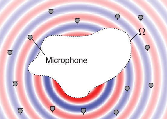
The diagram illustrates a concentric circular pattern representing signal propagation from a central microphone. Alternating red and blue rings radiate outward, with gray circular markers positioned at regular intervals along the outer rings. A dashed boundary encloses the microphone, and a symbol "Ω" is labeled near the upper-right periphery.
### Components/Axes
- **Central Microphone**: Labeled explicitly in black text within a white dashed boundary.
- **Concentric Rings**: Alternating red and blue bands radiating outward, suggesting signal strength or interference patterns.
- **Gray Circular Markers**: Positioned at intervals along the outer rings, likely representing sensor nodes or measurement points.
- **Ω Symbol**: Placed outside the outermost ring in the upper-right quadrant, possibly denoting a reference point or boundary condition.
### Detailed Analysis
- **Microphone**: Centralized within a white dashed region, acting as the signal source.
- **Color Coding**:
- Red rings may indicate high-intensity zones (e.g., constructive interference).
- Blue rings may represent low-intensity zones (e.g., destructive interference).
- **Gray Markers**: Uniformly spaced along the outer rings, suggesting systematic sampling points for signal analysis.
- **Ω Symbol**: Positioned at a 45° angle relative to the microphone, outside the outermost ring. Its placement implies a directional or boundary-related function (e.g., impedance matching, signal termination).
### Key Observations
1. **Symmetry**: The concentric rings exhibit radial symmetry, consistent with isotropic signal propagation.
2. **Marker Placement**: Gray markers are equidistant along the outer rings, indicating a structured measurement grid.
3. **Ω Symbol**: Its isolated position and lack of direct connection to the rings suggest a distinct role (e.g., environmental boundary, calibration reference).
### Interpretation
The diagram likely models acoustic or electromagnetic wave propagation from the microphone, with red/blue rings visualizing interference patterns. The gray markers could represent sensor nodes capturing signal data at specific radii. The Ω symbol may denote a critical parameter (e.g., characteristic impedance) or a physical boundary affecting wave behavior. The absence of a legend leaves color interpretation open, but the alternating pattern strongly implies constructive/destructive interference dynamics. The microphone’s central placement and dashed boundary emphasize its role as the primary signal source in this propagation model.