## Robotic Arm Task Diagram: Object Manipulation Setup
### Overview
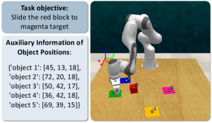
The image depicts a robotic arm interacting with colored blocks on a wooden surface. The task objective is to slide the red block to a magenta target. Auxiliary data provides coordinates for five objects, with a legend mapping colors to object identifiers.
### Components/Axes
- **Legend**: Located in the top-left corner, associating colors with object numbers:
- Red: Object 3
- Blue: Object 2
- Green: Object 1
- Pink: Object 4
- Yellow: Object 5
- **Object Positions**: Listed in a structured format with coordinates (x, y, z):
- Object 1: [45, 13, 18]
- Object 2: [72, 20, 18]
- Object 3: [50, 42, 17]
- Object 4: [36, 42, 18]
- Object 5: [69, 39, 15]
- **Diagram Elements**:
- Robotic arm (white/gray) positioned near the red block (Object 3).
- Colored blocks placed on distinct colored platforms (e.g., red block on green platform).
- Magenta target (unlabeled in data) implied as the destination for Object 3.
### Detailed Analysis
- **Object Coordinates**:
- Object 1 (green): [45, 13, 18]
- Object 2 (blue): [72, 20, 18]
- Object 3 (red): [50, 42, 17]
- Object 4 (pink): [36, 42, 18]
- Object 5 (yellow): [69, 39, 15]
- **Spatial Relationships**:
- Object 3 (red) is centrally located at [50, 42, 17], near Object 4 ([36, 42, 18]) and Object 2 ([72, 20, 18]).
- The robotic arm’s gripper is positioned above Object 3, suggesting active manipulation.
- Magenta target is not explicitly listed in the object positions, creating ambiguity about its coordinates.
### Key Observations
1. **Task Objective vs. Data**: The magenta target is referenced in the task description but absent from the object position list, indicating missing data.
2. **Red Block Proximity**: Object 3 (red) is equidistant in the y-axis (42) from Objects 1 and 4 but closer in x-axis to Object 4 (36 vs. 50).
3. **Robotic Arm Positioning**: The arm’s orientation suggests it is preparing to grasp Object 3, aligning with the task objective.
### Interpretation
The diagram illustrates a precision manipulation task requiring the robotic arm to relocate Object 3 (red block) to an unspecified magenta target. The provided coordinates suggest a 3D workspace, with Objects 1–5 distributed across the surface. The absence of the target’s coordinates introduces uncertainty, potentially requiring additional sensor data or assumptions for path planning. The robotic arm’s proximity to Object 3 implies readiness for execution, but the task’s success depends on resolving the target’s location.