## Diagram: Sound Source Localization
### Overview
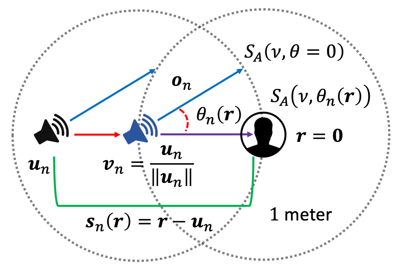
The image is a diagram illustrating a sound source localization scenario. It depicts two speakers, a listener, and various vectors representing sound propagation and spatial relationships. The diagram includes labels for vectors, angles, and distances, providing a visual representation of the parameters involved in sound source localization.
### Components/Axes
* **Speakers:** Two speaker icons are present, one black on the left and one blue in the center.
* **Listener:** A silhouette of a person's head is enclosed in a circle on the right.
* **Vectors:** Several labeled vectors are shown, including *u<sub>n</sub>*, *v<sub>n</sub>*, *o<sub>n</sub>*, and *s<sub>n</sub>(r)*.
* **Angle:** The angle *θ<sub>n</sub>(r)* is marked with a red arc.
* **Distance:** A distance of "1 meter" is indicated.
* **Circles:** Two dotted circles are centered on the speakers, representing a fixed distance (likely 1 meter).
* **Labels:**
* *u<sub>n</sub>*: Green line connecting the black speaker to the bottom of the listener circle.
* *v<sub>n</sub>* = *u<sub>n</sub>* / ||*u<sub>n</sub>*||: Located between the two speakers.
* *o<sub>n</sub>*: Blue line connecting both speakers to the listener.
* *s<sub>n</sub>(r)* = *r* - *u<sub>n</sub>*: Green line connecting the black speaker to the bottom of the listener circle.
* *θ<sub>n</sub>(r)*: Red arc representing the angle between the blue speaker and the listener.
* *r* = 0: Located near the listener.
* *S<sub>A</sub>(ν, θ = 0)*: Located above the listener.
* *S<sub>A</sub>(ν, θ<sub>n</sub>(r))* : Located near the listener.
### Detailed Analysis or Content Details
* **Vector *u<sub>n</sub>***: A green vector originates from the black speaker on the left and extends to a point near the listener.
* **Vector *v<sub>n</sub>***: This vector, defined as *u<sub>n</sub>* / ||*u<sub>n</sub>*||, is positioned between the two speakers. A horizontal line connects the blue speaker to the equation.
* **Vector *o<sub>n</sub>***: A blue vector originates from each speaker and extends towards the listener.
* **Vector *s<sub>n</sub>(r)***: A green vector is defined as *r* - *u<sub>n</sub>*.
* **Angle *θ<sub>n</sub>(r)***: A red arc indicates the angle between the vector from the blue speaker to the listener and a horizontal line extending from the blue speaker to the listener.
* **Listener Position *r***: The listener's position is defined as *r* = 0.
* **Sound Source Functions *S<sub>A</sub>***: Two sound source functions are defined: *S<sub>A</sub>(ν, θ = 0)* and *S<sub>A</sub>(ν, θ<sub>n</sub>(r))*.
* **Distance:** The distance between the speakers and the listener is implied to be related to the 1-meter circle radius.
### Key Observations
* The diagram illustrates the geometric relationships between sound sources (speakers) and a listener.
* Vectors represent sound propagation paths and spatial relationships.
* The angle *θ<sub>n</sub>(r)* represents the angular displacement of the listener relative to the blue speaker.
* The functions *S<sub>A</sub>(ν, θ = 0)* and *S<sub>A</sub>(ν, θ<sub>n</sub>(r))* likely represent sound source characteristics at different angles.
### Interpretation
The diagram provides a visual representation of the parameters involved in sound source localization. It shows how vectors, angles, and distances are used to model the spatial relationships between sound sources and a listener. The equations and labels provide a mathematical framework for understanding the sound propagation and localization process. The diagram suggests a scenario where the listener is at the origin (*r* = 0), and the sound sources are positioned around them. The angle *θ<sub>n</sub>(r)* is a key parameter in determining the direction of the sound source relative to the listener. The functions *S<sub>A</sub>(ν, θ = 0)* and *S<sub>A</sub>(ν, θ<sub>n</sub>(r))* likely represent the sound intensity or spectral characteristics at different angles, which can be used to localize the sound source.