## Diagram: Transformer Architecture
### Overview
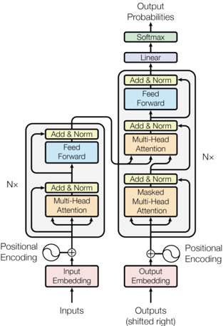
The image is a diagram illustrating the architecture of a transformer model, a type of neural network architecture primarily used in natural language processing. It shows the flow of data through the encoder and decoder components, highlighting key layers and processes.
### Components/Axes
* **Input:** The diagram takes "Inputs" at the bottom, which are fed into an "Input Embedding" layer.
* **Encoder Stack:** The left side of the diagram represents the encoder. It consists of the following layers, repeated N times:
* "Add & Norm" (yellow-green)
* "Feed Forward" (light blue)
* "Add & Norm" (yellow-green)
* "Multi-Head Attention" (light orange)
* **Decoder Stack:** The right side of the diagram represents the decoder. It consists of the following layers, repeated N times:
* "Add & Norm" (yellow-green)
* "Feed Forward" (light blue)
* "Add & Norm" (yellow-green)
* "Multi-Head Attention" (light orange)
* "Add & Norm" (yellow-green)
* "Masked Multi-Head Attention" (light orange)
* **Output:** The output of the decoder is fed into a "Linear" layer (light blue), followed by a "Softmax" layer (yellow-green), resulting in "Output Probabilities" at the top. The input to the decoder is "Output Embedding".
* **Positional Encoding:** Both the input and output embeddings are combined with "Positional Encoding" before being fed into the encoder and decoder stacks, respectively.
* **Nx:** Indicates that the blocks are repeated N times.
### Detailed Analysis
* **Input Embedding:** The "Inputs" are first processed by an "Input Embedding" layer (light red).
* **Positional Encoding (Left):** A sine wave symbol represents positional encoding, which is added to the input embedding.
* **Encoder Stack (Left):** The encoder stack consists of a "Multi-Head Attention" layer (light orange) followed by an "Add & Norm" layer (yellow-green), then a "Feed Forward" layer (light blue) followed by another "Add & Norm" layer (yellow-green). This entire block is repeated N times.
* **Output Embedding:** The "Outputs (shifted right)" are processed by an "Output Embedding" layer (light red).
* **Positional Encoding (Right):** A sine wave symbol represents positional encoding, which is added to the output embedding.
* **Decoder Stack (Right):** The decoder stack consists of a "Masked Multi-Head Attention" layer (light orange) followed by an "Add & Norm" layer (yellow-green), then a "Multi-Head Attention" layer (light orange) followed by an "Add & Norm" layer (yellow-green), then a "Feed Forward" layer (light blue) followed by another "Add & Norm" layer (yellow-green). This entire block is repeated N times.
* **Output Probabilities:** The output of the decoder stack is processed by a "Linear" layer (light blue) and then a "Softmax" layer (yellow-green) to produce "Output Probabilities".
### Key Observations
* The encoder and decoder stacks have similar structures, with the decoder including an additional "Masked Multi-Head Attention" layer.
* Positional encoding is added to both the input and output embeddings.
* The "Add & Norm" layers appear frequently throughout the architecture, likely representing residual connections and layer normalization.
### Interpretation
The diagram illustrates the core architecture of a transformer model, which is designed to handle sequence-to-sequence tasks. The encoder processes the input sequence, and the decoder generates the output sequence. The multi-head attention mechanism allows the model to attend to different parts of the input sequence when generating the output. The positional encoding provides information about the position of each word in the sequence, which is important for understanding the meaning of the sequence. The repetition of the encoder and decoder blocks (N times) allows the model to learn complex relationships between the input and output sequences. The masking in the "Masked Multi-Head Attention" layer prevents the decoder from attending to future tokens in the output sequence, which is necessary for autoregressive generation.