## Diagram: Global Fan-Out
### Overview
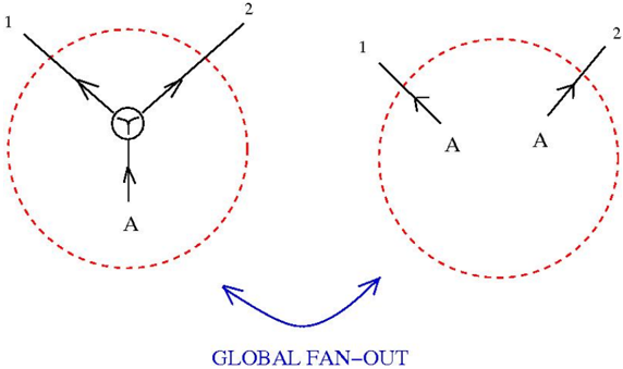
The image depicts a diagram illustrating a "GLOBAL FAN-OUT" process. It shows two circular regions connected by a curved arrow, representing a transformation or relationship between the two states. The left circle contains a central node with three incoming and outgoing connections, while the right circle shows two separate connections.
### Components/Axes
* **Circles:** Two dashed red circles, one on the left and one on the right. These circles likely represent a system or boundary.
* **Arrows:** Black arrows indicate the direction of flow or interaction.
* **Nodes:** The left circle contains a central node with a "Y" shape inside a circle.
* **Labels:** The numbers "1" and "2" are present at the ends of the lines entering/exiting the circles. The letter "A" is present near the bottom of each circle.
* **Connecting Arrow:** A blue curved arrow connects the two circles, pointing from left to right.
* **Text:** The text "GLOBAL FAN-OUT" is located below the connecting arrow.
### Detailed Analysis
**Left Circle:**
* Two lines labeled "1" and "2" enter the circle from the top-left and top-right, respectively. Each line has an arrow indicating flow towards the central node.
* The central node is a circle containing a "Y" shape.
* One line exits the circle from the bottom of the central node, with an arrow pointing downwards.
* The letter "A" is located below the exiting line.
**Right Circle:**
* Two lines exit the circle from the top-left and top-right, labeled "1" and "2" respectively. Each line has an arrow pointing away from the center of the circle.
* The letter "A" is located near the base of each line.
**Connecting Arrow:**
* A blue curved arrow connects the right side of the left circle to the left side of the right circle.
* The text "GLOBAL FAN-OUT" is located below the arrow.
### Key Observations
* The left circle represents a convergence of two inputs into a single output.
* The right circle represents a divergence of two outputs.
* The "GLOBAL FAN-OUT" process transforms a single output into two separate outputs.
### Interpretation
The diagram illustrates a "GLOBAL FAN-OUT" process, where a single input "A" (represented by the output of the left circle) is transformed into two separate outputs "A" (represented by the outputs of the right circle). The central node in the left circle likely represents a processing or distribution point. The numbers "1" and "2" could represent different channels or destinations for the outputs. The diagram suggests a system where a single signal or resource is distributed to multiple recipients.