## Diagram: Global Fan-Out Process Flow
### Overview
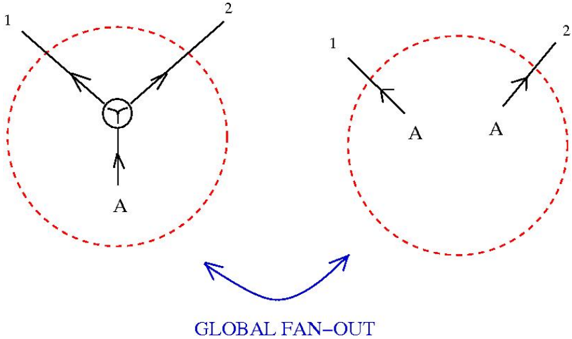
The image depicts two interconnected diagrams illustrating a data flow or process transformation labeled "GLOBAL FAN-OUT." The left diagram (Diagram 1) shows a central node with three outgoing arrows, while the right diagram (Diagram 2) shows two incoming arrows converging on a labeled point. A blue bidirectional arrow connects the diagrams, emphasizing the global nature of the process.
### Components/Axes
- **Diagram 1 (Left)**:
- Central node with three outgoing arrows labeled **1**, **2**, and **A**.
- Enclosed in a red dashed circle.
- **Diagram 2 (Right)**:
- Two incoming arrows labeled **1** and **2**, both pointing to a labeled point **A**.
- Enclosed in a red dashed circle.
- **Global Connection**:
- Blue bidirectional arrow labeled **"GLOBAL FAN-OUT"** connects Diagram 1 and Diagram 2.
- **Text Elements**:
- "GLOBAL FAN-OUT" in uppercase blue text at the bottom center.
### Detailed Analysis
- **Diagram 1**:
- The central node acts as a source or origin point.
- Arrows **1** and **2** likely represent distinct data streams or processes.
- Arrow **A** may indicate a third process or output originating from the same node.
- **Diagram 2**:
- Arrows **1** and **2** converge on point **A**, suggesting aggregation, merging, or transformation of inputs into a unified output.
- The red dashed circle implies a boundary or processing stage.
- **Global Fan-Out**:
- The blue arrow indicates bidirectional interaction or synchronization between the two diagrams.
- The term "FAN-OUT" suggests a distribution or expansion of data/processes from a central point.
### Key Observations
1. **Reduction in Outputs**: Diagram 1 has three outputs (1, 2, A), while Diagram 2 consolidates two inputs into a single output (A).
2. **Symmetry in Labeling**: Both diagrams use labels **1**, **2**, and **A**, but their roles differ (outputs vs. inputs).
3. **Bidirectional Flow**: The blue arrow implies a feedback loop or mutual dependency between the diagrams.
### Interpretation
The diagram likely represents a system where:
- **Diagram 1** models the initial distribution or generation of processes/data streams (1, 2, A).
- **Diagram 2** represents a subsequent stage where these streams are filtered, merged, or transformed into a unified output (A).
- The "GLOBAL FAN-OUT" mechanism ensures coordination or synchronization between the initial distribution and final convergence, possibly indicating a distributed computing architecture or data pipeline.
The use of identical labels (**1**, **2**, **A**) in both diagrams suggests a cyclical or iterative process, where outputs from one stage become inputs for another. The red dashed circles may symbolize isolated processing units or stages within a larger system.