## Diagram: Sequential Collision Simulation of Two Balls in a Rectangular Enclosure
### Overview
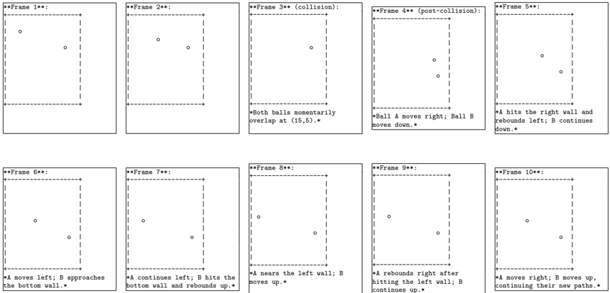
The image displays a sequence of 10 frames, arranged in two rows of five, illustrating the movement and collision of two balls (labeled A and B) within a rectangular boundary. The diagram is a technical simulation, likely for physics or computer graphics, showing discrete time steps. The style is a simple black-and-white line drawing with dashed borders representing the enclosure walls.
### Components/Axes
* **Enclosure:** Each frame depicts a rectangular area defined by a dashed line border.
* **Objects:** Two small circles represent the balls. They are not visually distinguished by color or pattern in the drawing; their identities (A or B) are defined solely by the accompanying text descriptions.
* **Text Labels:**
* **Frame Titles:** Each frame is titled above its rectangle (e.g., "**Frame 1**:", "**Frame 3** (collision):").
* **Descriptive Text:** Most frames have a line of text below the rectangle describing the action occurring in that frame.
* **Coordinate System:** No explicit axes or grid are shown. One coordinate pair is mentioned in text: the collision point at (15,5).
### Detailed Analysis
The sequence describes the motion of two balls, A and B. The analysis below follows the frame-by-frame text and inferred visual positions.
* **Frame 1:** Two balls are present. One is in the upper-left quadrant, the other in the center-right area. No descriptive text.
* **Frame 2:** The balls have moved. One is near the top-center, the other near the center-right. No descriptive text.
* **Frame 3 (collision):** The text states: "*Both balls momentarily overlap at (15,5).*" Visually, a single circle is shown near the center of the frame, indicating the collision point.
* **Frame 4 (post-collision):** The text states: "*Ball A moves right; Ball B moves down.*" Visually, two circles are now shown, separated vertically. One is in the upper-right quadrant (presumed A), the other in the lower-right quadrant (presumed B).
* **Frame 5:** The text states: "*A hits the right wall and rebounds left; B continues down.*" Visually, one circle is near the right wall, slightly above the vertical center (A). The other is near the bottom-right corner (B).
* **Frame 6:** The text states: "*A moves left; B approaches the bottom wall.*" Visually, one circle is in the center-left area (A). The other is very close to the bottom wall, right of center (B).
* **Frame 7:** The text states: "*A continues left; B hits the bottom wall and rebounds up.*" Visually, one circle is near the left wall, slightly below the vertical center (A). The other is just above the bottom wall, right of center (B).
* **Frame 8:** The text states: "*A nears the left wall; B moves up.*" Visually, one circle is very close to the left wall, near the vertical center (A). The other is in the lower-right quadrant, moving upward (B).
* **Frame 9:** The text states: "*A rebounds right after hitting the left wall; B continues up.*" Visually, one circle is just to the right of the left wall, near the vertical center (A). The other is in the center-right area, moving upward (B).
* **Frame 10:** The text states: "*A moves right; B moves up, continuing their new paths.*" Visually, one circle is in the center-left area (A). The other is in the upper-right quadrant (B).
### Key Observations
1. **Collision Event:** The central event is the collision at Frame 3 at coordinates (15,5). This is the only point where the balls' paths intersect.
2. **Post-Collision Trajectories:** After collision, the balls move in distinctly different directions: A moves horizontally (right, then left after wall hits), while B moves vertically (down, then up after a wall hit).
3. **Wall Interactions:** Both balls interact with the enclosure boundaries. Ball A collides with the right wall (Frame 5) and left wall (Frame 9). Ball B collides with the bottom wall (Frame 7). Each collision results in a rebound, reversing the component of velocity perpendicular to the wall.
4. **Path Independence:** After their respective wall rebounds, the balls appear to continue in straight-line paths until the end of the sequence (Frame 10), suggesting no further collisions occur within this timeframe.
5. **Visual Ambiguity:** The balls are not visually labeled. Their identification relies entirely on the textual descriptions, which must be cross-referenced with the inferred motion from the previous frame to maintain consistency.
### Interpretation
This diagram is a pedagogical or technical illustration of **elastic collision and reflection in a two-dimensional, bounded space**. It demonstrates several key physics principles:
* **Conservation of Momentum (Implied):** The collision at Frame 3 changes the velocities of both balls. The subsequent motions suggest an exchange of momentum, with A gaining horizontal motion and B gaining vertical motion post-collision.
* **Specular Reflection:** The interactions with the walls model perfect elastic reflection, where the angle of incidence equals the angle of reflection. This is evident in the clean reversals of direction upon wall contact.
* **Discrete Time Simulation:** The frame-by-frame breakdown is characteristic of a computational simulation (e.g., using a game loop or physics engine) where positions are updated at fixed time intervals.
* **System Behavior:** The simulation shows how simple rules (constant velocity, elastic collision with objects and boundaries) can generate complex, predictable trajectories from a single interaction event. The final frame shows the system evolving along these new, stable paths.
**Notable Anomaly/Clarification:** The text in Frame 3 states the balls "overlap," which in a physical simulation would imply a single point of contact. The visual representation uses a single circle, which is a simplification. In a more detailed diagram, one might expect to see the balls just touching. The coordinate (15,5) provides the only quantitative spatial data in the entire sequence.