\n
## Diagram: Data-steering and Multiply-Accumulate Hardware
### Overview
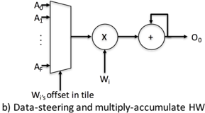
The image depicts a block diagram illustrating a data-steering and multiply-accumulate hardware architecture. It shows the flow of input data (A0 to Af) through a data steering mechanism, a multiplier, and an accumulator to produce an output (O0). The diagram is labeled "b) Data-steering and multiply-accumulate HW" at the bottom.
### Components/Axes
The diagram consists of the following components:
* **Input Data:** Represented by A0, A1, ..., Af. These are vertically stacked inputs.
* **Data Steering Block:** A rectangular block receiving the input data (A0 to Af) and an offset signal (Wi's offset in tile).
* **Multiplier:** A circle labeled "x", receiving input from the data steering block and a weight signal (Wi).
* **Accumulator:** A circle labeled "+", receiving input from the multiplier and a feedback loop from its output.
* **Output:** Represented by O0, the output of the accumulator.
* **Offset Input:** Labeled "Wi's offset in tile", connected to the data steering block.
* **Weight Input:** Labeled "Wi", connected to the multiplier.
### Detailed Analysis or Content Details
The diagram illustrates a computational flow:
1. Input data A0 through Af are fed into the data steering block.
2. The data steering block receives an offset signal "Wi's offset in tile".
3. The output of the data steering block is multiplied by a weight "Wi" in the multiplier.
4. The result of the multiplication is added to the previous output of the accumulator in the accumulator.
5. The output of the accumulator (O0) is fed back into the accumulator for the next accumulation step.
There are no numerical values or specific scales present in the diagram. The diagram is conceptual and does not provide quantitative data.
### Key Observations
The diagram highlights a common hardware architecture used in digital signal processing and machine learning for performing multiply-accumulate operations. The data steering block suggests a mechanism for selecting or routing specific input data based on the offset signal. The feedback loop in the accumulator indicates an iterative accumulation process.
### Interpretation
This diagram represents a fundamental building block in many hardware accelerators, particularly those used for neural network computations. The data steering mechanism allows for efficient data reuse and reduces memory access, while the multiply-accumulate unit performs the core computation. The feedback loop in the accumulator is essential for accumulating the weighted inputs, which is a key operation in neural network layers. The "Wi's offset in tile" suggests that the data is processed in tiles, which is a common technique for handling large datasets in hardware. The diagram demonstrates a pipelined architecture where data flows sequentially through the different stages (data steering, multiplication, and accumulation). This architecture is designed to maximize throughput and minimize latency.