## Diagram: Binaural Audio Processing with Transformer Encoders
### Overview
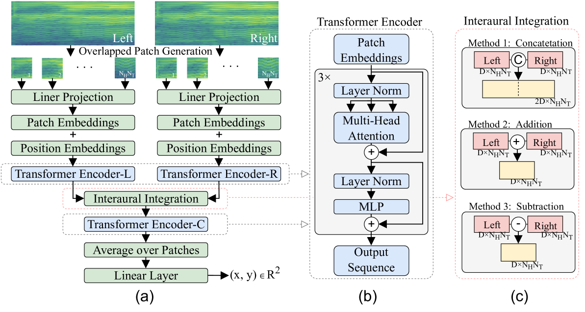
The image presents a block diagram illustrating a binaural audio processing system using transformer encoders. It is divided into three main sections: (a) feature extraction and interaural integration, (b) the structure of a transformer encoder, and (c) three methods for interaural integration.
### Components/Axes
**Section (a): Feature Extraction and Interaural Integration**
* **Input:** Spectrograms labeled "Left" and "Right".
* **Overlapped Patch Generation:** Indicates the division of the spectrograms into overlapping patches. The patches are labeled with "N<sub>H</sub>N<sub>T</sub>".
* **Linear Projection:** A linear transformation applied to the patches.
* **Patch Embeddings:** The output of the linear projection, representing the embedded patches.
* **Position Embeddings:** Positional information added to the patch embeddings.
* **Transformer Encoder-L:** Transformer encoder for the left channel.
* **Transformer Encoder-R:** Transformer encoder for the right channel.
* **Interaural Integration:** Combines information from the left and right channels.
* **Transformer Encoder-C:** Transformer encoder applied after interaural integration.
* **Average over Patches:** Averages the output over all patches.
* **Linear Layer:** A final linear layer that maps the output to (x, y) ∈ R<sup>2</sup>.
**Section (b): Transformer Encoder**
* **Patch Embeddings:** Input to the transformer encoder.
* **3x:** Indicates that the following block is repeated three times.
* **Layer Norm:** Layer normalization.
* **Multi-Head Attention:** Multi-head attention mechanism.
* **MLP:** Multilayer Perceptron.
* **Output Sequence:** The output of the transformer encoder.
**Section (c): Interaural Integration Methods**
* **Method 1: Concatenation:** Concatenates the left and right channel features.
* Left: D x N<sub>H</sub>N<sub>T</sub>
* Right: D x N<sub>H</sub>N<sub>T</sub>
* Output: 2D x N<sub>H</sub>N<sub>T</sub>
* **Method 2: Addition:** Adds the left and right channel features.
* Left: D x N<sub>H</sub>N<sub>T</sub>
* Right: D x N<sub>H</sub>N<sub>T</sub>
* Output: D x N<sub>H</sub>N<sub>T</sub>
* **Method 3: Subtraction:** Subtracts the right channel features from the left channel features.
* Left: D x N<sub>H</sub>N<sub>T</sub>
* Right: D x N<sub>H</sub>N<sub>T</sub>
* Output: D x N<sub>H</sub>N<sub>T</sub>
### Detailed Analysis
**Section (a):**
1. The process begins with left and right channel spectrograms.
2. These spectrograms are divided into overlapping patches, each of size N<sub>H</sub>N<sub>T</sub>.
3. Each patch undergoes linear projection, resulting in patch embeddings.
4. Positional embeddings are added to the patch embeddings to incorporate sequential information.
5. The left and right channel embeddings are processed by separate transformer encoders (Transformer Encoder-L and Transformer Encoder-R).
6. The outputs of these encoders are then integrated using one of the methods described in section (c).
7. The integrated features are passed through another transformer encoder (Transformer Encoder-C).
8. The output is averaged over all patches.
9. Finally, a linear layer maps the averaged output to a 2D coordinate (x, y) ∈ R<sup>2</sup>.
**Section (b):**
1. The transformer encoder consists of a series of repeated blocks (3x).
2. Each block includes layer normalization, multi-head attention, and an MLP.
3. Residual connections are used to improve training stability.
4. The output of the transformer encoder is a sequence of embeddings.
**Section (c):**
1. Three methods for interaural integration are presented: concatenation, addition, and subtraction.
2. Concatenation doubles the feature dimension, while addition and subtraction maintain the original dimension.
3. The input to each method consists of left and right channel features, each with dimensions D x N<sub>H</sub>N<sub>T</sub>.
### Key Observations
* The system processes binaural audio by extracting features from left and right channel spectrograms.
* Transformer encoders are used to model the temporal dependencies in the audio signals.
* Interaural integration is performed to combine information from the left and right channels.
* Three different methods for interaural integration are explored.
### Interpretation
The diagram illustrates a system for binaural audio processing that leverages transformer encoders. The system aims to extract relevant features from the left and right audio channels, integrate them effectively, and map the resulting representation to a 2D space. The use of transformer encoders allows the system to capture long-range dependencies in the audio signals, while the different interaural integration methods provide flexibility in how the left and right channel information is combined. The final linear layer suggests that the system might be used for tasks such as sound localization or spatial audio analysis, where the output (x, y) represents a spatial coordinate.