## Microfluidic Device and Particle Dynamics
### Overview
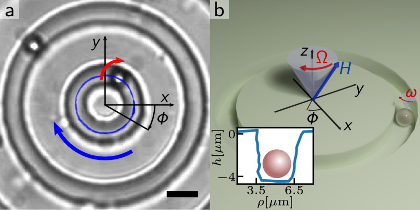
The image presents a two-part illustration of a microfluidic device and the dynamics of a particle within it. Part (a) shows a top-down view of the microfluidic structure, including concentric circular channels and coordinate axes. Part (b) provides a 3D schematic of the device, illustrating the magnetic field, rotation, and a cross-sectional view of a particle trapped in a channel.
### Components/Axes
**Part (a): Microfluidic Structure (Top View)**
* **Concentric Circular Channels:** The image shows several concentric circular channels etched into a substrate.
* **Coordinate Axes:** A coordinate system is superimposed on the image, with the x and y axes intersecting at the center of the circles.
* **Angle Φ:** An angle Φ is marked between the x-axis and a radial line.
* **Arrows:** A red arrow indicates rotation around the y-axis, and a blue arrow indicates rotation around the center of the circular channels.
* **Scale Bar:** A black scale bar is present at the bottom-right of the image.
**Part (b): 3D Schematic and Cross-Section**
* **3D Schematic:** A 3D representation of the microfluidic device shows a circular channel on a rotating platform.
* **Magnetic Field (H):** A blue arrow labeled "H" represents the magnetic field direction.
* **Rotation (Ω and ω):** A red arrow labeled "Ω" indicates the rotation of the magnetic field around the z-axis, and a red arrow labeled "ω" indicates the rotation of the platform.
* **Coordinate Axes:** A coordinate system is shown, with x, y, and z axes.
* **Angle Φ:** An angle Φ is marked between the x-axis and a radial line.
* **Cross-Section:** An inset shows a cross-sectional view of the channel with a particle inside.
* **Vertical Axis:** Labeled "h[µm]", ranging from -4 to 0.
* **Horizontal Axis:** Labeled "ρ[µm]", ranging from 3.5 to 6.5.
* **Channel Profile:** A blue line shows the depth profile of the channel.
* **Particle:** A pink sphere represents the particle trapped within the channel.
### Detailed Analysis
**Part (a): Microfluidic Structure (Top View)**
* The concentric circular channels appear to be etched into a flat substrate.
* The red arrow indicates a rotation around the y-axis.
* The blue arrow indicates a rotation around the center of the circular channels.
**Part (b): 3D Schematic and Cross-Section**
* The magnetic field (H) is oriented at an angle to the z-axis.
* The platform rotates with an angular velocity ω.
* The cross-sectional plot shows the depth (h) of the channel as a function of radial position (ρ).
* The channel depth is approximately -4 µm.
* The channel width is approximately 6.5 µm - 3.5 µm = 3 µm.
* The particle is centered within the channel.
### Key Observations
* The microfluidic device is designed to trap and manipulate particles using a combination of magnetic fields and rotation.
* The cross-sectional plot provides information about the channel geometry and particle position.
### Interpretation
The image illustrates a system for manipulating microparticles within a microfluidic device. The combination of a rotating platform and a magnetic field allows for precise control over the particle's motion. The cross-sectional plot provides a detailed view of the channel geometry and the particle's confinement within the channel. This type of system could be used for a variety of applications, including drug delivery, diagnostics, and materials science. The angles and rotations are critical to understanding the forces acting on the particle. The depth profile of the channel is also important for understanding the particle's confinement.