\n
## Diagram: Microfluidic Vortex and Particle Trapping
### Overview
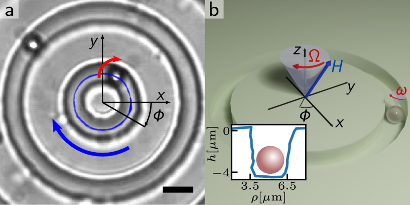
The image presents two panels (a and b) illustrating a microfluidic vortex generated within a circular chamber and the trapping of a particle within it. Panel (a) shows a top-down view of the vortex flow pattern, while panel (b) provides a 3D representation of the vortex and a cross-sectional profile of the chamber's height.
### Components/Axes
**Panel a:**
* **Coordinate System:** A Cartesian coordinate system is overlaid on the image with the x and y axes labeled. An additional radial coordinate, Φ (phi), is also indicated.
* **Flow Visualization:** Red and blue arrows depict the direction of fluid flow, forming a vortex pattern.
* **Scale Bar:** A black scale bar is present in the bottom-left corner, indicating a length scale (though the exact length is not specified).
**Panel b:**
* **Coordinate System:** A Cartesian coordinate system (x, y) and a z-axis are shown.
* **Vortex Representation:** A gray, conical shape represents the vortex.
* **Magnetic Field:** A blue arrow labeled "H" indicates the direction of a magnetic field.
* **Rotation Vectors:** A red arrow labeled "Ω" represents the angular velocity of the vortex, and another red arrow labeled "ω" indicates the rotation of the trapped particle.
* **Height Profile:** A graph is embedded in the bottom-left corner, plotting height (h) in micrometers (µm) against radial distance (ρ) in micrometers (µm). The axes are labeled "h [µm]" and "ρ [µm]".
### Detailed Analysis or Content Details
**Panel a:**
The vortex flow pattern is clearly visible as concentric rings. The red arrows indicate a clockwise rotation near the outer edge of the vortex, while the blue arrows indicate a counter-clockwise rotation closer to the center. The flow appears to converge towards the center of the circular chamber.
**Panel b:**
* **Height Profile:** The embedded graph shows a cross-section of the chamber's height. The height is approximately 0 µm at ρ = 3.5 µm and dips to approximately -4 µm at ρ = 6.5 µm, indicating a concave shape at the bottom of the chamber. The profile shows a rapid increase in height around ρ = 6.5 µm.
* **Vortex Orientation:** The vortex is oriented with its apex pointing upwards along the z-axis.
* **Magnetic Field and Rotation:** The magnetic field (H) is aligned with the z-axis. The angular velocity of the vortex (Ω) and the particle (ω) are both oriented in the same direction.
### Key Observations
* The vortex is generated within a circular microfluidic chamber.
* A particle is trapped near the center of the vortex.
* The chamber has a non-flat bottom, as evidenced by the height profile.
* A magnetic field is present and may be involved in the particle trapping mechanism.
### Interpretation
The diagram illustrates a microfluidic system designed to trap particles using a vortex flow. The vortex is likely generated by applying a tangential force to the fluid within the chamber. The particle is drawn into the center of the vortex and held there by the balancing forces of the fluid flow and potentially a magnetic field. The concave shape of the chamber bottom, as shown in the height profile, may contribute to the stability of the vortex and the particle trapping. The magnetic field (H) could be used to manipulate the particle's position or orientation within the vortex. The coordinate systems provide a framework for quantifying the flow dynamics and particle behavior. The diagram suggests a potential application in microfluidic particle sorting, concentration, or analysis.