## Network Diagram: Node and Connection Analysis
### Overview
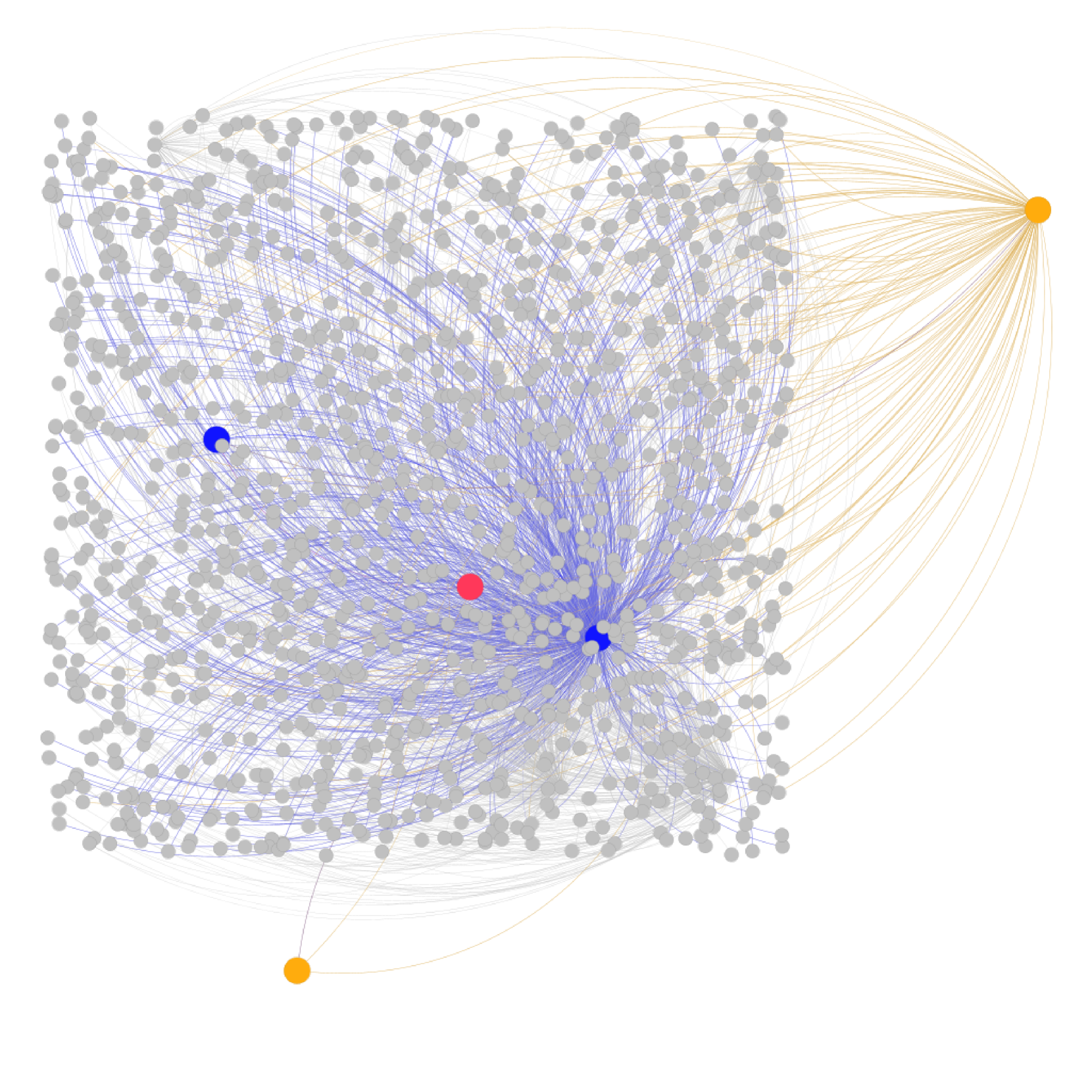
The image depicts a complex network diagram with nodes and edges representing connections. The diagram uses color-coded nodes and edges to distinguish between different types of entities and relationships. The network appears to have a hierarchical structure with central and peripheral nodes.
### Components/Axes
- **Nodes**:
- **Gray Nodes**: Labeled as "General Nodes" in the legend (right side of the diagram).
- **Blue Node**: Labeled as "Primary Hub" in the legend.
- **Red Node**: Labeled as "Secondary Hub" in the legend.
- **Orange Node**: Labeled as "External Connection" in the legend.
- **Edges**:
- **Blue Edges**: Labeled as "Internal Links" in the legend.
- **Orange Edges**: Labeled as "External Links" in the legend.
- **Legend**: Positioned on the right side of the diagram, with color-coded labels for nodes and edges.
### Detailed Analysis
1. **Primary Hub (Blue Node)**:
- Located centrally in the diagram.
- Connected to numerous gray nodes via blue edges ("Internal Links").
- Has the highest density of connections, indicating it is the central node of the network.
2. **Secondary Hub (Red Node)**:
- Positioned slightly to the left of the center.
- Connected to a subset of gray nodes via blue edges.
- Has fewer connections than the Primary Hub but more than the External Connection.
3. **External Connection (Orange Node)**:
- Located on the far right of the diagram.
- Connected to gray nodes via orange edges ("External Links").
- Has the fewest connections overall, suggesting a peripheral role.
4. **General Nodes (Gray Nodes)**:
- Scattered throughout the diagram.
- Mostly connected via blue edges to the Primary and Secondary Hubs.
- A subset of gray nodes on the right are connected to the External Connection via orange edges.
### Key Observations
- The network is **centralized**, with the Primary Hub (blue node) acting as the dominant node.
- The Secondary Hub (red node) serves as a secondary point of connection but is less central than the Primary Hub.
- The External Connection (orange node) is isolated to the right side, indicating a distinct external relationship.
- Gray nodes are predominantly internal but show some external connectivity via the orange node.
### Interpretation
This diagram represents a network with a clear hierarchy:
- The **Primary Hub** (blue node) is the core of the network, managing most internal connections.
- The **Secondary Hub** (red node) acts as a secondary node, likely handling overflow or specialized tasks.
- The **External Connection** (orange node) represents an external entity, possibly a partner or third-party system, with limited internal interactions.
- The **General Nodes** (gray nodes) are peripheral entities, mostly engaged in internal communication but with some external links.
The structure suggests a system where the Primary Hub is critical for maintaining network cohesion, while the External Connection operates independently. The Secondary Hub bridges the Primary Hub and peripheral nodes, indicating a tiered relationship. The orange edges highlight a distinct external subsystem, possibly for specialized or isolated operations.