## Diagram: Black Box with Inputs and Outputs
### Overview
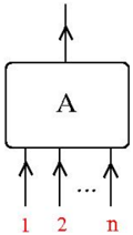
The image shows a diagram of a black box labeled "A" with one input and multiple outputs. The outputs are labeled 1, 2, and n, suggesting a series of outputs.
### Components/Axes
* **Black Box:** A rectangle with rounded corners, labeled "A" in the center.
* **Input:** A single arrow pointing into the top of the black box.
* **Outputs:** Three arrows pointing out of the bottom of the black box. The arrows are labeled 1, 2, and n. The labels 1, 2, and n are in red. An ellipsis (...) is between the second and third output arrows, indicating that there are more outputs than shown.
### Detailed Analysis
* The diagram represents a system or function (A) that takes one input and produces multiple outputs.
* The ellipsis indicates that the number of outputs can vary or is not explicitly defined.
* The red labels 1, 2, and n likely represent indices or identifiers for each output.
### Key Observations
* The diagram is a simplified representation of a system with multiple outputs.
* The use of an ellipsis suggests a potentially large or variable number of outputs.
### Interpretation
The diagram illustrates a process where a single input is transformed or distributed into multiple outputs. This could represent a variety of systems, such as a signal splitter, a data processing unit, or a function that generates multiple results from a single input. The black box representation emphasizes that the internal workings of the system are not specified or relevant to the diagram's purpose, which is to show the input-output relationship.