## Diagram: Abstract Flowchart with Central Node
### Overview
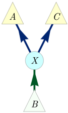
The image displays a simple, abstract flowchart or network diagram consisting of four geometric shapes connected by directional arrows. The diagram illustrates a hierarchical or process-based relationship where a central node (X) acts as an intermediary between a source (B) and two destinations (A and C).
### Components/Axes
The diagram contains the following labeled components, positioned as follows:
* **Top-Left:** A yellow, upward-pointing triangle labeled with the letter **"A"**.
* **Top-Right:** A yellow, upward-pointing triangle labeled with the letter **"C"**.
* **Center:** A light blue circle labeled with the letter **"X"**.
* **Bottom-Center:** A white, upward-pointing triangle labeled with the letter **"B"**.
**Connections (Arrows):**
* A **dark blue arrow** originates from the top of circle **X** and points to the base of triangle **A**.
* A **dark blue arrow** originates from the top of circle **X** and points to the base of triangle **C**.
* A **green arrow** originates from the top of triangle **B** and points to the bottom of circle **X**.
### Detailed Analysis
The diagram establishes a clear directional flow:
1. **Source:** Triangle **B** is the starting point.
2. **Intermediary/Processor:** The green arrow indicates that **B** provides input to, or activates, the central circle **X**.
3. **Divergent Output:** From **X**, two dark blue arrows branch out, indicating that **X** sends output, directs, or influences both triangles **A** and **C**.
The color coding is consistent: source/destination triangles are yellow (A, C) or white (B), the central node is blue (X), and the arrows are colored by their function (green for input to X, dark blue for output from X).
### Key Observations
* **Symmetry:** The diagram is vertically symmetrical. Triangles **A** and **C** are identical in shape, color, and label style, positioned equidistant from the central axis.
* **Central Node:** Circle **X** is the only circular element and the only element with a blue fill, emphasizing its unique role as a hub or junction.
* **Arrow Direction:** All arrows point upward, suggesting a bottom-up flow of information, material, or influence.
* **Labeling:** All labels (**A**, **B**, **C**, **X**) are single, uppercase, italicized letters in a serif font.
### Interpretation
This diagram is a conceptual model representing a **one-to-many distribution** or **mediated relationship**. The data suggests that **B** is a primary source or initiator whose effect is not direct but is processed or routed through a central entity **X** before reaching the end points **A** and **C**.
**Possible real-world analogies include:**
* **Information Flow:** A news source (B) sends a report to an editor (X), who then publishes it in two different publications (A and C).
* **Supply Chain:** A raw material supplier (B) ships to a central manufacturer (X), who produces finished goods for two distinct retailers (A and C).
* **Control System:** A sensor (B) sends data to a controller (X), which then issues commands to two separate actuators (A and C).
The absence of specific data or metrics indicates this is a high-level schematic meant to illustrate structure and relationship, not quantitative performance. The key takeaway is the **indispensable, central role of node X**; without it, there is no connection from B to A or C. The identical treatment of A and C implies they are of equal status or receive identical treatment from X.