## Device Operation Diagrams
### Overview
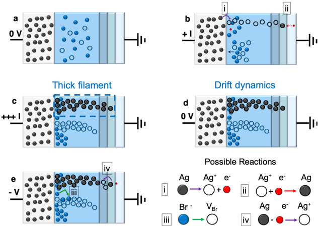
The image presents a series of diagrams illustrating the operation of a device under varying voltage conditions. The diagrams depict the movement of ions and electrons within the device, leading to the formation and dissolution of conductive filaments. The image also includes a legend describing possible reactions within the device.
### Components/Axes
Each diagram (a-e) shows a device consisting of two electrodes separated by a material. The left electrode is represented by a collection of black circles, and the right electrode is represented by a vertical line connected to a circuit symbol. The material between the electrodes contains blue circles, white circles, and in some cases, black circles.
* **Labels:**
* Diagrams are labeled a, b, c, d, and e.
* Voltage levels are indicated next to each diagram: 0 V (a, d), +I (b), +++I (c), -V (e).
* Titles: Thick filament, Drift dynamics, Possible Reactions
* **Legend (Possible Reactions):** Located at the bottom-right of the image.
* Reaction i: Ag (black circle) -> Ag+ (white circle) + e- (red circle)
* Reaction ii: Ag+ (white circle) + e- (red circle) -> Ag (black circle)
* Reaction iii: Br- (blue circle) -> VBr (white circle)
* Reaction iv: Ag (black circle) + e- (red circle) -> Ag+ (white circle)
* **Particles:**
* Ag (Silver): Represented by black circles.
* Ag+ (Silver Ion): Represented by white circles.
* e- (Electron): Represented by red circles.
* Br- (Bromide Ion): Represented by blue circles.
* VBr (Bromide Vacancy): Represented by white circles.
### Detailed Analysis or ### Content Details
* **Diagram a (0 V):**
* Voltage: 0 V
* Distribution: Blue circles (Br-) are evenly distributed within the material. White circles (Ag+) are sparsely distributed. Black circles (Ag) are concentrated in the left electrode.
* Trend: No significant movement or reaction is depicted.
* **Diagram b (+I):**
* Voltage: +I
* Distribution: Blue circles (Br-) move away from the left electrode. White circles (Ag+) move towards the right electrode. Red circles (e-) are present near the left electrode.
* Arrows: An arrow indicates the movement of blue circles away from the left electrode. Another arrow indicates the movement of white circles towards the right electrode.
* Reactions: Reaction i is shown near the left electrode, and reaction ii is shown near the right electrode.
* **Diagram c (+++I):**
* Voltage: +++I
* Distribution: A thick filament of black circles (Ag) has formed, spanning from the left electrode towards the right electrode. Blue circles (Br-) are concentrated at the bottom of the material.
* Region: A dashed blue rectangle labeled "Thick filament" highlights the region where the black circles are concentrated.
* **Diagram d (0 V):**
* Voltage: 0 V
* Distribution: Black circles (Ag) are concentrated near the left electrode, forming a partial filament. Blue circles (Br-) are concentrated at the bottom of the material.
* Title: "Drift dynamics" suggests the diagram illustrates the movement of ions.
* **Diagram e (-V):**
* Voltage: -V
* Distribution: The filament of black circles (Ag) is dissolving. Blue circles (Br-) are becoming more evenly distributed.
* Arrows: An arrow indicates the movement of blue circles. Reaction iii is shown near the left electrode, and reaction iv is shown near the right electrode.
### Key Observations
* The diagrams illustrate the formation and dissolution of a conductive filament under different voltage conditions.
* The movement of ions (Ag+ and Br-) plays a crucial role in the filament formation and dissolution process.
* The legend provides the chemical reactions associated with the movement of ions and electrons.
### Interpretation
The diagrams demonstrate the operation of a resistive switching device. Applying a positive voltage (+I or +++I) causes the formation of a conductive filament composed of silver (Ag) atoms. This filament bridges the gap between the electrodes, allowing current to flow. The formation of the filament is driven by the migration of silver ions (Ag+) and the reduction of silver ions to silver atoms. Applying a negative voltage (-V) causes the dissolution of the filament, breaking the conductive path. This process is driven by the oxidation of silver atoms to silver ions. The movement of bromide ions (Br-) also plays a role in the process. The "Drift dynamics" diagram suggests that the movement of ions is influenced by the electric field. The "Thick filament" diagram shows that under high positive voltage, a robust conductive path is formed. The device's ability to switch between conductive and non-conductive states makes it suitable for memory and other electronic applications.