## Diagram: Bipartite Network with Central Hub
### Overview
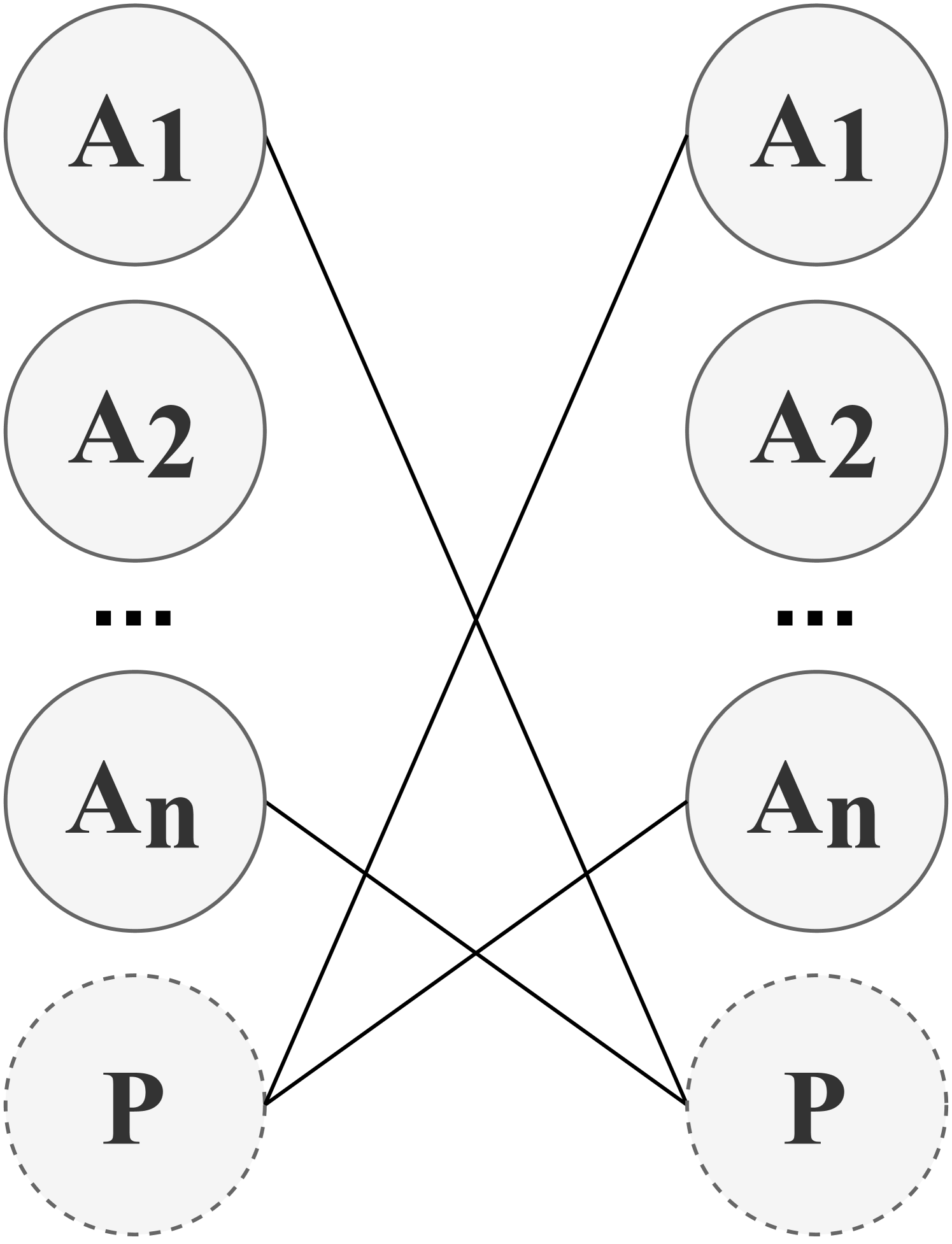
The diagram depicts a symmetrical bipartite network structure with two mirrored columns of labeled nodes (A1 to An) connected by intersecting lines. At the bottom, two dashed nodes labeled "P" serve as central connection points. The network forms an X-shaped intersection pattern between the two columns.
### Components/Axes
- **Nodes**:
- Left column: A1, A2, ..., An (solid circles)
- Right column: A1, A2, ..., An (solid circles)
- Bottom: P (dashed circles, two instances)
- **Connections**:
- Each A node connects to:
1. Its mirrored counterpart (A1-A1, A2-A2, etc.)
2. Both P nodes via crossing lines
- P nodes connect to all A nodes in both columns
- **Visual Elements**:
- Solid black lines for A-A and A-P connections
- Dashed gray circles for P nodes
- X-shaped intersection pattern in central region
### Detailed Analysis
- **Node Distribution**:
- Left column: n nodes (A1-An)
- Right column: n nodes (A1-An)
- Bottom: 2 P nodes
- **Connection Density**:
- Each A node has 3 connections (1 mirrored A + 2 P nodes)
- Total connections: 2n (A-A pairs) + 4n (A-P connections) = 6n
- **Symmetry**:
- Perfect bilateral symmetry in node labeling and connections
- Mirrored A node pairs maintain identical connection patterns
### Key Observations
1. Central P nodes act as universal connectors to all A nodes
2. A-A connections only occur between mirrored pairs
3. Dashed P nodes suggest different properties vs solid A nodes
4. X-shaped intersections create four quadrants of overlapping connections
### Interpretation
This diagram likely represents:
1. **System Architecture**: A mirrored system (left/right) with a central processing unit (P) handling cross-column interactions
2. **Network Topology**: A bipartite graph with additional universal connectors (P nodes)
3. **Process Flow**: Data/operations flow between mirrored components (A-A) and central processing (A-P)
4. **Redundancy**: Dual P nodes may provide failover capabilities
The symmetrical design emphasizes balanced interactions between mirrored components, while the central P nodes create a unified interface layer. The dashed P nodes might represent abstract entities (e.g., protocols, services) versus concrete components (A nodes). The X-shaped intersections suggest complex interdependencies requiring coordinated processing through the central hub.