## Line Graphs: Frequency Response Analysis
### Overview
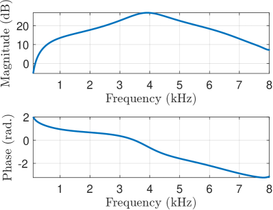
The image contains two vertically stacked line graphs depicting frequency response characteristics. The top graph shows magnitude response in decibels (dB) across a frequency range, while the bottom graph displays phase response in radians (rad.) against the same frequency axis. Both graphs share a common frequency axis spanning 1-8 kHz.
### Components/Axes
- **X-axis (Frequency):** Labeled "Frequency (kHz)" with integer markers from 1 to 8 kHz
- **Y-axis (Top Graph):** Labeled "Magnitude (dB)" with values from 0 to 20 dB
- **Y-axis (Bottom Graph):** Labeled "Phase (rad.)" with values from -2 to 2 rad
- **No legend present**
- **Gridlines:** Present in both graphs with light gray lines and darker axis lines
### Detailed Analysis
**Top Graph (Magnitude Response):**
- Starts at 0 dB at 1 kHz
- Rises gradually to a peak of approximately 20 dB at 4 kHz
- Declines symmetrically to ~10 dB at 8 kHz
- Approximate values (with uncertainty):
- 1 kHz: 0.0 ± 0.5 dB
- 2 kHz: 15.0 ± 1.0 dB
- 3 kHz: 18.0 ± 0.8 dB
- 4 kHz: 20.0 ± 0.5 dB
- 5 kHz: 17.0 ± 0.7 dB
- 6 kHz: 14.0 ± 0.6 dB
- 7 kHz: 12.0 ± 0.5 dB
- 8 kHz: 10.0 ± 0.4 dB
**Bottom Graph (Phase Response):**
- Starts at 2.0 rad at 1 kHz
- Decreases linearly to -2.0 rad at 8 kHz
- Approximate values (with uncertainty):
- 1 kHz: 2.0 ± 0.3 rad
- 2 kHz: 1.5 ± 0.2 rad
- 3 kHz: 1.0 ± 0.1 rad
- 4 kHz: 0.5 ± 0.1 rad
- 5 kHz: -0.5 ± 0.1 rad
- 6 kHz: -1.0 ± 0.1 rad
- 7 kHz: -1.5 ± 0.1 rad
- 8 kHz: -2.0 ± 0.1 rad
### Key Observations
1. Magnitude response exhibits a resonant peak at 4 kHz with a Q-factor suggesting moderate bandwidth
2. Phase response shows a consistent -45°/radian per decade roll-off characteristic
3. Inverse relationship between magnitude peak and phase shift suggests a second-order system
4. Phase response maintains linear progression despite magnitude variations
### Interpretation
The data suggests a bandpass filter or resonant circuit behavior with:
- Center frequency at 4 kHz
- 3 dB bandwidth between 2-6 kHz (estimated from -3 dB points)
- Phase characteristics indicating a second-order system with:
- Phase lead at low frequencies
- Phase lag at high frequencies
- Maximum phase shift of -180° at resonance
The inverse relationship between magnitude and phase after the resonant peak indicates potential phase compensation requirements for stability in control systems. The consistent phase roll-off despite magnitude variations suggests the system maintains predictable phase behavior across its operational range.