## Diagram: Network Architecture
### Overview
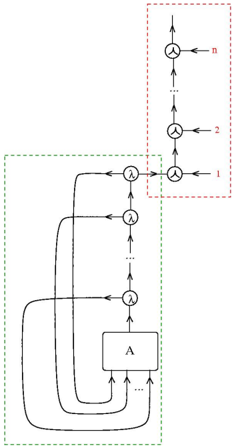
The image presents a diagram of a network architecture, likely representing a computational or information processing system. It features interconnected components, including a central block labeled "A," several circular nodes with the symbol "λ," and a series of nodes connected to external inputs labeled 1, 2, ..., n. The diagram uses arrows to indicate the direction of flow or data transmission.
### Components/Axes
* **Central Block:** A rectangular block labeled "A" at the bottom-center of the diagram.
* **Circular Nodes:** Several circular nodes, each containing the symbol "λ," are positioned vertically above the central block.
* **Input Nodes:** A series of nodes, each connected to an external input labeled with numbers 1, 2, ..., n, are located on the right side of the diagram.
* **Arrows:** Arrows indicate the direction of flow or data transmission between the components.
* **Green Dashed Box:** Encloses the central block "A" and the circular nodes with "λ" below the input nodes.
* **Red Dashed Box:** Encloses the input nodes labeled 1, 2, ..., n.
### Detailed Analysis
* **Central Block "A":** The central block "A" has multiple inputs at its bottom and a single output at its top.
* **Circular Nodes with "λ":** These nodes are arranged vertically above the central block. Each node receives an input from below and has two outputs: one directed upwards and another looping back towards the central block "A."
* **Input Nodes (1, 2, ..., n):** These nodes are arranged vertically on the right side of the diagram. Each node receives an external input (labeled 1, 2, ..., n) and connects to the main flow path.
* **Flow Direction:** The arrows indicate that the flow originates from the central block "A," passes through the circular nodes with "λ," and eventually connects to the input nodes (1, 2, ..., n). The loops from the circular nodes with "λ" back to the central block "A" suggest a feedback mechanism.
* **Positioning:** The red dashed box is located on the top-right of the diagram. The green dashed box is located on the left side of the diagram.
### Key Observations
* The diagram illustrates a network with a central processing unit ("A") and feedback loops.
* The input nodes (1, 2, ..., n) provide external inputs to the network.
* The circular nodes with "λ" likely represent some form of processing or transformation of the data.
### Interpretation
The diagram likely represents a recurrent neural network or a similar computational architecture. The central block "A" could represent a core processing unit, while the circular nodes with "λ" could represent layers or units within the network. The feedback loops suggest that the network's output is fed back into the input, allowing it to learn and adapt over time. The input nodes (1, 2, ..., n) provide external data to the network, which is then processed and transformed by the network's internal components. The architecture suggests a system capable of processing sequential data or learning complex patterns.