## Diagram: Directed Graph with Node Annotations
### Overview
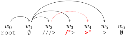
The image displays a directed graph (or tree-like structure) consisting of seven nodes arranged horizontally in a linear sequence. Each node is labeled with a "w" followed by a subscript index (0 through 6). Below each node label is a secondary annotation or symbol. The nodes are connected by a series of directed edges (arrows), which are of two distinct types: solid black lines and dashed red lines. The diagram appears to represent a sequence, process, or dependency structure, possibly from a computational, linguistic, or formal systems context.
### Components/Axes
* **Nodes (Primary Labels):** Seven nodes, positioned left to right, labeled: `w₀`, `w₁`, `w₂`, `w₃`, `w₄`, `w₅`, `w₆`.
* **Node Annotations (Secondary Labels):** Directly beneath each primary node label is a symbol or word:
* `w₀`: `root`
* `w₁`: `∅` (the empty set symbol)
* `w₂`: `///>`
* `w₃`: `/*>`
* `w₄`: `>*`
* `w₅`: `>`
* `w₆`: `∅`
* **Edges (Arrows):** Directed arrows connecting nodes. Two visual styles are present:
* **Solid Black Arrows:** Represent one type of relationship or flow.
* **Dashed Red Arrows:** Represent a different, possibly secondary or conditional, type of relationship.
* **Spatial Layout:** All nodes are aligned on a single horizontal baseline. Arrows curve above this baseline to connect non-adjacent nodes.
### Detailed Analysis
**Node-by-Node Breakdown (Left to Right):**
1. **Node `w₀` (Position: Far Left):**
* Primary Label: `w₀`
* Annotation: `root`
* Outgoing Edges: One solid black arrow to `w₁`.
2. **Node `w₁`:**
* Primary Label: `w₁`
* Annotation: `∅`
* Outgoing Edges: Multiple solid black arrows originating from this node. It connects to `w₂`, `w₃`, `w₄`, and `w₅`.
3. **Node `w₂`:**
* Primary Label: `w₂`
* Annotation: `///>`
* Outgoing Edges: One solid black arrow to `w₃`.
4. **Node `w₃`:**
* Primary Label: `w₃`
* Annotation: `/*>`
* Outgoing Edges: One solid black arrow to `w₄`.
5. **Node `w₄`:**
* Primary Label: `w₄`
* Annotation: `>*`
* Outgoing Edges: One solid black arrow to `w₅`.
6. **Node `w₅`:**
* Primary Label: `w₅`
* Annotation: `>`
* Outgoing Edges: One solid black arrow to `w₆`.
7. **Node `w₆` (Position: Far Right):**
* Primary Label: `w₆`
* Annotation: `∅`
**Edge (Connection) Analysis:**
* **Solid Black Arrow Path:** A primary chain exists: `w₀` → `w₁` → `w₂` → `w₃` → `w₄` → `w₅` → `w₆`. This forms a linear backbone.
* **Additional Solid Black Arrows from `w₁`:** Node `w₁` has direct, long-range connections to `w₃`, `w₄`, and `w₅`, bypassing intermediate nodes. This creates a fan-out structure from `w₁`.
* **Dashed Red Arrows:** Two dashed red arrows are present:
1. From `w₂` to `w₄`.
2. From `w₃` to `w₅`.
These create "skip" connections that parallel the solid black path but are visually distinct.
### Key Observations
1. **Structural Hierarchy:** `w₀` is explicitly labeled "root," establishing it as the origin point of the graph.
2. **Fan-Out Hub:** Node `w₁` (annotated with `∅`) is a major hub, with five outgoing edges (four solid black, one implicit in the main chain). It connects directly to most subsequent nodes.
3. **Pattern in Annotations:** The annotations for nodes `w₂` through `w₅` (`///>`, `/*>`, `>*`, `>`) appear to be a sequence of symbols that may represent operations, states, or transformations, potentially decreasing in complexity or changing form.
4. **Dual Connection Types:** The presence of both solid black and dashed red arrows suggests two distinct types of relationships or processes operating between the same set of nodes. The red dashed arrows consistently connect a node to the node two positions ahead (`w₂`→`w₄`, `w₃`→`w₅`).
5. **Terminal Nodes:** Both the start (`w₀`) and end (`w₆`) nodes are annotated with unique labels (`root` and `∅` respectively), while `w₁` also shares the `∅` annotation with `w₆`.
### Interpretation
This diagram likely models a **sequential process with parallel or conditional pathways**. The solid black arrows define a primary, step-by-step workflow from `root` to a terminal `∅` state. The fan-out from `w₁` suggests it is a critical decision or distribution point early in the process.
The dashed red arrows introduce an alternative or secondary pathway. Their consistent "skip-one" pattern (`n` → `n+2`) could represent:
* A lookahead or preview function.
* An error-checking or validation step that compares non-adjacent stages.
* A parallel processing thread that operates on a different timescale or logic.
The symbolic annotations (`///>`, `/*>`, etc.) are highly suggestive of **formal language syntax, comment markers in code, or state machine transitions**. For example, `/*>` resembles the start of a block comment in C-like languages, while `>` could be a prompt or output symbol. The `∅` (empty set) symbol at `w₁` and `w₆` might denote an initial "empty" or "null" state and a final "cleared" or "completed" state, respectively.
**In essence, the graph maps a transformation from a defined root, through a series of symbolic states or operations (with both linear and branching pathways), to a final empty state.** The dual-edge types imply the system being modeled has both a primary execution flow and a secondary monitoring, dependency, or alternative execution flow.