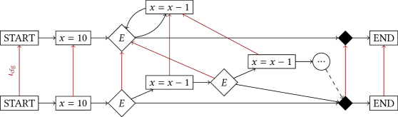
## Control Flow Graph: Two Parallel Paths
### Overview
The image depicts a control flow graph with two parallel execution paths. Each path starts with an initialization step (x = 10), proceeds through a conditional check (E), and potentially involves decrementing x (x = x - 1) before reaching the end. The paths are connected by control flow edges, some of which are highlighted in red.
### Components/Axes
* **Nodes:**
* `START`: Initial node for each path.
* `x = 10`: Assignment node, initializing the variable x to 10.
* `E`: Conditional check node.
* `x = x - 1`: Decrement node, reducing the value of x by 1.
* `END`: Terminal node for each path.
* `...`: Ellipsis node, indicating a potential continuation or loop.
* **Edges:**
* Black edges: Represent standard control flow within each path.
* Red edges: Represent control flow between the two paths, labeled as "tcfg".
* **Layout:** The graph is structured with two parallel paths, one above the other. The nodes are arranged horizontally within each path, with edges connecting them.
### Detailed Analysis
**Top Path:**
1. `START` (top-left) -> `x = 10` (top-center-left): The path begins with the "START" node, which flows into the assignment "x = 10".
2. `x = 10` -> `E` (top-center): The assignment node flows into the conditional check "E".
3. `E` -> `x = x - 1` (top-center): From the conditional check, the path can flow into the decrement node "x = x - 1".
4. `x = x - 1` -> `E`: There is a loop back from the decrement node to the conditional check.
5. `E` -> Diamond (top-right): The conditional check can also flow to a black diamond.
6. Diamond -> `END` (top-right): The black diamond flows into the "END" node.
7. `x = x - 1` -> `E`: There is a loop back from the decrement node to the conditional check.
**Bottom Path:**
1. `START` (bottom-left) -> `x = 10` (bottom-center-left): The path begins with the "START" node, which flows into the assignment "x = 10".
2. `x = 10` -> `E` (bottom-center): The assignment node flows into the conditional check "E".
3. `E` -> `x = x - 1` (bottom-center): From the conditional check, the path can flow into the decrement node "x = x - 1".
4. `x = x - 1` -> `...` (center-right): The decrement node flows into an ellipsis node.
5. `E` -> Diamond (bottom-right): The conditional check can also flow to a black diamond.
6. Diamond -> `END` (bottom-right): The black diamond flows into the "END" node.
7. `...` -> Diamond (bottom-right): The ellipsis node flows into the black diamond with a dashed line.
**Inter-Path Connections (Red Edges):**
1. `START` (bottom-left) -> `START` (top-left): A red edge connects the "START" nodes of the two paths, labeled "tcfg".
2. `x = 10` (bottom-center-left) -> `x = 10` (top-center-left): A red edge connects the "x = 10" nodes of the two paths.
3. `E` (bottom-center) -> `x = x - 1` (top-center): A red edge connects the conditional check of the bottom path to the decrement node of the top path.
4. `x = x - 1` (bottom-center) -> `E` (top-center): A red edge connects the decrement node of the bottom path to the conditional check of the top path.
5. `E` (top-center) -> Diamond (bottom-right): A red edge connects the conditional check of the top path to the black diamond of the bottom path.
6. Diamond (top-right) -> Diamond (bottom-right): A red edge connects the black diamond of the top path to the black diamond of the bottom path.
### Key Observations
* The two paths are largely independent but have several connections via red edges.
* The conditional check "E" and the decrement operation "x = x - 1" are central to the control flow in both paths.
* The ellipsis node in the bottom path suggests a potential loop or continuation that is not fully specified.
### Interpretation
The control flow graph represents two parallel processes that interact with each other. The red edges indicate dependencies or synchronization points between the paths. The conditional checks "E" likely represent decision points that determine the execution path within each process. The decrement operations "x = x - 1" suggest that the variable x is being modified during the execution of each path. The "tcfg" label on the red edges between the start nodes and the assignment nodes suggests that these edges represent control flow related to thread creation or context switching. The ellipsis node in the bottom path indicates that the process may continue beyond the depicted nodes, potentially involving a loop or further computations. The connections between the conditional checks and decrement operations of the two paths suggest that the processes may influence each other's behavior based on the value of x.