## Flowchart: Conditional Loop with Control Flow Graph (CFG) Dependencies
### Overview
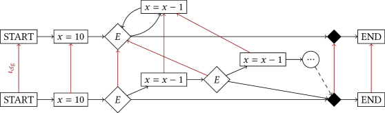
The diagram illustrates a conditional loop structure with control flow dependencies. It features two identical starting points (`START`), a variable initialization (`x = 10`), a decision node (`E`), iterative decrement operations (`x = x - 1`), and two terminal nodes (`END`). Red arrows labeled "cfg" connect the `START` nodes to the first `x = 10` node, indicating control flow graph dependencies.
---
### Components/Axes
- **Nodes**:
- **START**: Two identical nodes at the top-left, initiating the process.
- **x = 10**: Rectangular node where variable `x` is initialized to 10.
- **E**: Diamond-shaped decision node (likely a condition check).
- **x = x - 1**: Rectangular node representing iterative decrement of `x`.
- **END**: Two terminal nodes at the top-right and bottom-right, marking process completion.
- **Edges**:
- Solid black arrows: Primary control flow paths.
- Red "cfg" arrows: Control flow graph dependencies between `START` and `x = 10`.
- Dashed gray arrow: Alternative/exceptional path from `x = x - 1` to `END`.
---
### Detailed Analysis
1. **Initialization**:
- Both `START` nodes feed into `x = 10` via red "cfg" arrows, suggesting parallel or dependent initialization paths.
2. **Decision Loop**:
- From `x = 10`, control flows to decision node `E`.
- If `E` evaluates to true, the loop continues: `x = x - 1` → `E` (repeated until condition fails).
- If `E` evaluates to false, control proceeds directly to `END` (top-right).
3. **Alternative Termination**:
- A dashed gray arrow bypasses the loop entirely, connecting the second `x = x - 1` node directly to `END` (bottom-right), indicating an exceptional exit condition.
---
### Key Observations
- **Loop Behavior**: The loop decrements `x` from 10 until `E` evaluates to false. The exact condition for `E` is unspecified but likely checks `x` against a threshold (e.g., `x > 0`).
- **CFG Dependencies**: The red "cfg" arrows imply that the two `START` nodes share a common dependency on the `x = 10` initialization.
- **Divergent Termination**: Two `END` nodes suggest the process can terminate under distinct conditions (normal loop exit vs. exceptional case).
---
### Interpretation
This flowchart models a **conditional iteration** with control flow dependencies, common in programming or algorithm design. The "cfg" arrows highlight how multiple entry points (`START`) converge on a shared initialization step (`x = 10`), emphasizing modularity or parallelism. The dual `END` nodes reflect scenario-dependent termination, while the dashed arrow introduces an edge case (e.g., early termination due to an error or external signal). The structure aligns with **Peircean abductive reasoning**, where the loop represents hypothesis testing (`x` as a variable under iterative refinement) and `E` acts as a pragmatic criterion for accepting or rejecting the hypothesis.