\n
## Diagram: Flow Diagram with Nodes and Arrows
### Overview
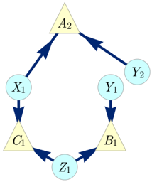
The image depicts a flow diagram consisting of six nodes (circles and triangles) connected by directed arrows. The nodes are labeled X₁, Y₁, Z₁, A₂, B₁, and C₁. The arrows indicate the direction of flow or relationship between the nodes. The diagram appears to represent a process or system with interconnected stages.
### Components/Axes
The diagram consists of the following components:
* **Nodes:**
* X₁ (Circle)
* Y₁ (Circle)
* Z₁ (Circle)
* A₂ (Triangle)
* B₁ (Triangle)
* C₁ (Triangle)
* **Arrows:** Directed arrows connecting the nodes, indicating flow direction.
### Detailed Analysis or Content Details
The diagram shows the following connections:
1. A₂ points to X₁
2. X₁ points to C₁
3. C₁ points to Z₁
4. Z₁ points to B₁
5. B₁ points to Y₁
6. Y₁ points to A₂
7. A₂ points to Y₂
8. Y₂ points to Y₁
The nodes alternate between circular and triangular shapes. The labels are subscripted with numbers.
### Key Observations
The diagram forms a closed loop with the nodes A₂, X₁, C₁, Z₁, B₁, and Y₁ in sequence. There is an additional node Y₂ that is only pointed to by A₂ and points to Y₁. The diagram suggests a cyclical process or feedback loop.
### Interpretation
The diagram likely represents a system or process where elements influence each other in a cyclical manner. The alternating shapes of the nodes (circles and triangles) might indicate different types of elements or stages within the process. The inclusion of Y₂ as a separate node connected to A₂ and Y₁ suggests a potential branching or feedback mechanism within the loop. The diagram is abstract and does not provide specific information about the nature of the process or the meaning of the nodes, but it clearly illustrates the interconnectedness and cyclical nature of the system. The diagram could represent a state machine, a chemical reaction pathway, or a simplified model of a complex system. Without further context, the precise meaning of the diagram remains open to interpretation.