## Block Diagram: Communication System Overview
### Overview
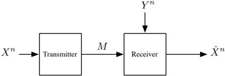
The image depicts a simplified block diagram of a communication system. It illustrates the flow of signals between a transmitter and a receiver, including the channel and signal transformations.
### Components/Axes
- **Components**:
- **Transmitter**: A rectangular block labeled "Transmitter" positioned on the left side of the diagram.
- **Receiver**: A rectangular block labeled "Receiver" positioned on the right side of the diagram.
- **Channel**: A horizontal arrow labeled "M" connecting the transmitter and receiver, representing the communication medium.
- **Signals**:
- **Input Signal**: Labeled $ X^n $, entering the transmitter from the left.
- **Output Signal**: Labeled $ Y^n $, exiting the receiver and pointing upward.
- **Estimated Signal**: Labeled $ \hat{X}^n $, exiting the receiver and pointing to the right.
### Detailed Analysis
- **Signal Flow**:
1. The input signal $ X^n $ is processed by the transmitter.
2. The processed signal travels through the channel $ M $ to the receiver.
3. The receiver processes the signal, producing two outputs:
- $ Y^n $, which is transmitted upward (possibly representing feedback or a secondary output).
- $ \hat{X}^n $, the estimated version of the original input signal $ X^n $, transmitted to the right.
### Key Observations
- The diagram emphasizes the bidirectional relationship between the transmitter and receiver, with the channel $ M $ acting as a mediator.
- The use of $ \hat{X}^n $ suggests the receiver performs estimation or reconstruction of the original signal, potentially accounting for noise or distortion in $ M $.
- No numerical values or quantitative data are present; the diagram focuses on structural relationships.
### Interpretation
This diagram represents a foundational model of a communication system, highlighting the roles of the transmitter, receiver, and channel. The inclusion of $ \hat{X}^n $ implies that the receiver employs algorithms (e.g., filtering, decoding) to recover the original signal from the received $ Y^n $. The upward arrow for $ Y^n $ may indicate a feedback loop or a separate output for monitoring purposes. The absence of explicit noise or error terms suggests an idealized scenario, though real-world implementations would likely include such factors. The diagram underscores the importance of signal processing in ensuring accurate transmission and reception.