## Diagram: Proof Generation and Verification
### Overview
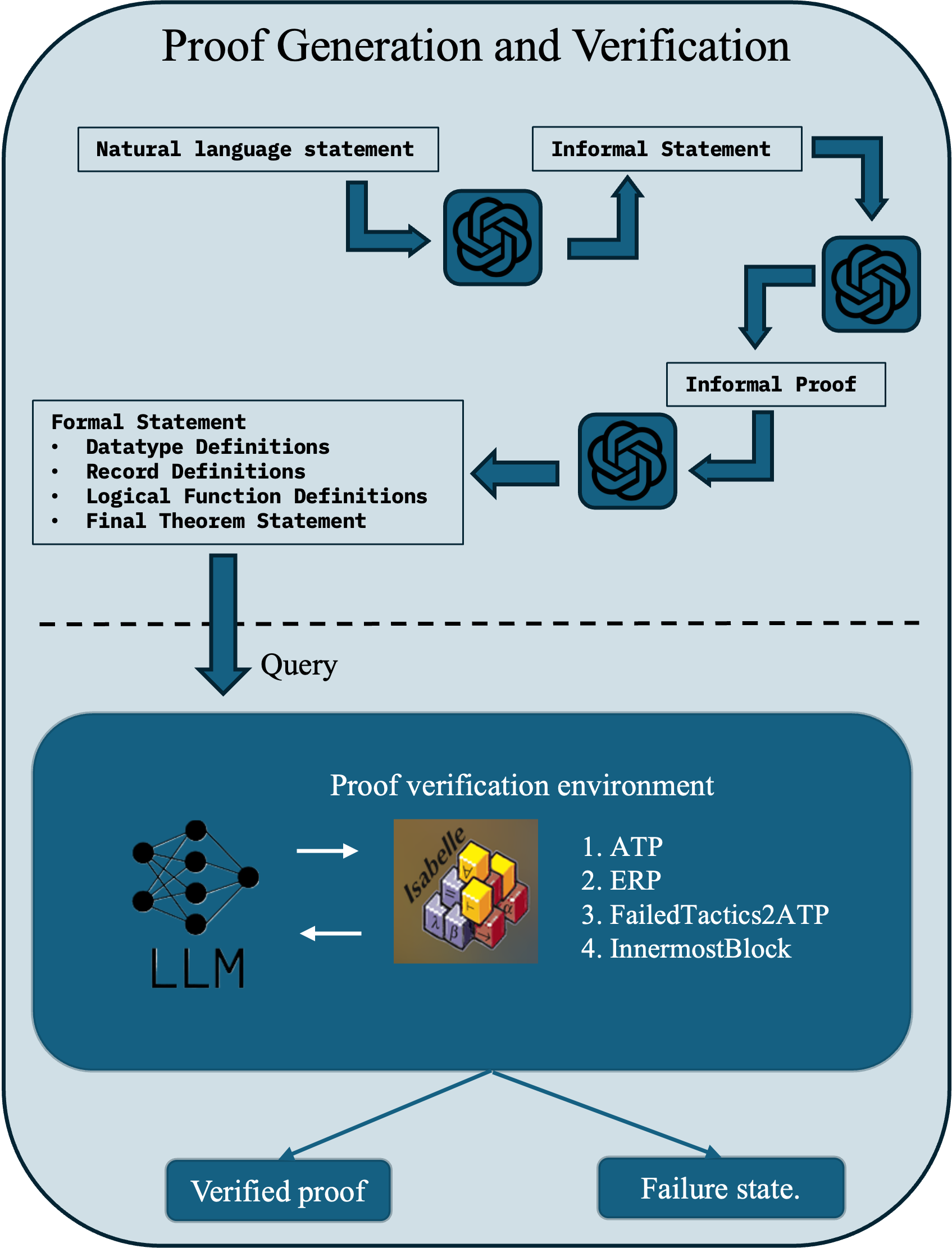
The image is a diagram illustrating the process of proof generation and verification. It outlines the steps from a natural language statement to a verified proof or a failure state, involving components like LLM (Large Language Model) and Isabelle.
### Components/Axes
* **Title:** Proof Generation and Verification
* **Boxes:**
* Natural language statement (top-left)
* Informal Statement (top-right)
* Formal Statement (left, below "Natural language statement")
* Datatype Definitions
* Record Definitions
* Logical Function Definitions
* Final Theorem Statement
* Informal Proof (right, below "Informal Statement")
* Query (center, between the upper and lower sections)
* Proof verification environment (bottom, large rounded rectangle)
* LLM (Large Language Model, bottom-left within "Proof verification environment")
* Isabelle (center within "Proof verification environment")
* 1. ATP
* 2. ERP
* 3. FailedTactics2ATP
* 4. InnermostBlock
* Verified proof (bottom-left)
* Failure state (bottom-right)
* **Arrows:** Dark blue arrows indicate the flow of information and processes.
* **Symbols:** The diagram uses a stylized symbol resembling the OpenAI logo at several points in the flow.
* **Divider:** A dashed line separates the proof generation steps from the proof verification environment.
### Detailed Analysis
1. **Flow Initiation:** The process begins with a "Natural language statement" and an "Informal Statement".
2. **Transformation:** Both statements are transformed via the OpenAI-like symbol. The "Informal Statement" is transformed into "Informal Proof" through another OpenAI-like symbol.
3. **Formalization:** The "Natural language statement" is transformed into a "Formal Statement" which includes:
* Datatype Definitions
* Record Definitions
* Logical Function Definitions
* Final Theorem Statement
4. **Query:** The "Formal Statement" is then converted into a "Query".
5. **Proof Verification Environment:** The "Query" enters the "Proof verification environment", which contains:
* An LLM (Large Language Model) represented by a neural network diagram.
* Isabelle, represented by a stack of colored blocks with symbols on them (λ, β, ∀, ∃, α, ⊢).
* A list of verification methods:
* 1. ATP
* 2. ERP
* 3. FailedTactics2ATP
* 4. InnermostBlock
6. **Outcomes:** The process results in either a "Verified proof" or a "Failure state".
### Key Observations
* The diagram illustrates a pipeline for converting natural language statements into formal proofs and verifying them using automated tools.
* The use of an LLM suggests an automated approach to proof generation and verification.
* Isabelle, a theorem prover, is a key component in the verification environment.
* The diagram highlights the possibility of failure in the proof verification process.
### Interpretation
The diagram depicts an automated system for generating and verifying mathematical or logical proofs. It starts with human-readable inputs (natural language and informal statements), transforms them into a formal representation, and then uses an LLM and Isabelle to attempt to verify the proof. The system can either successfully verify the proof or result in a failure state, indicating that the proof could not be verified. This suggests a system designed to automate the rigorous process of mathematical proof, potentially reducing human error and increasing efficiency.