# Technical Document: State Machine Flow Diagrams
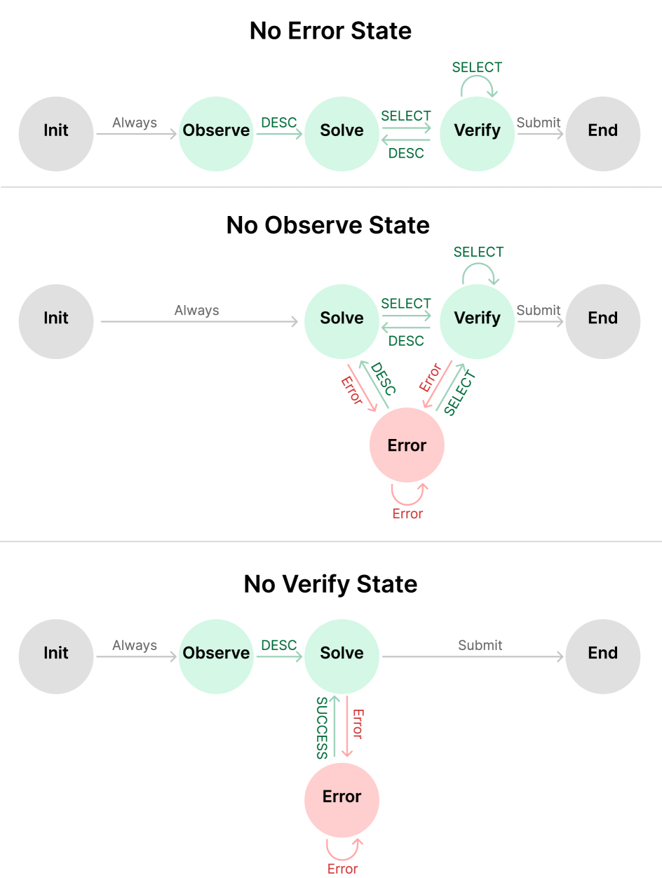
This document provides a comprehensive extraction of the data and logic contained within the provided image. The image consists of three distinct state machine diagrams, each representing a different operational configuration: **No Error State**, **No Observe State**, and **No Verify State**.
---
## 1. Diagram Overview: No Error State
This diagram represents a linear progression of states without an explicit error-handling node.
### Components (Nodes)
* **Init** (Grey): The starting state.
* **Observe** (Light Green): The first operational state.
* **Solve** (Light Green): The second operational state.
* **Verify** (Light Green): The final operational state before completion.
* **End** (Grey): The terminal state.
### State Transitions (Flow)
1. **Init $\rightarrow$ Observe**: Triggered by "Always".
2. **Observe $\rightarrow$ Solve**: Triggered by "DESC".
3. **Solve $\rightarrow$ Verify**: Triggered by "SELECT".
4. **Verify $\rightarrow$ Solve**: Triggered by "DESC" (allows returning to the previous state).
5. **Verify $\rightarrow$ Verify**: Self-loop triggered by "SELECT".
6. **Verify $\rightarrow$ End**: Triggered by "Submit".
---
## 2. Diagram Overview: No Observe State
This diagram removes the "Observe" state and introduces a dedicated "Error" state with complex feedback loops.
### Components (Nodes)
* **Init** (Grey): The starting state.
* **Solve** (Light Green): The primary operational state.
* **Verify** (Light Green): The validation state.
* **Error** (Light Red): A state for handling failures.
* **End** (Grey): The terminal state.
### State Transitions (Flow)
1. **Init $\rightarrow$ Solve**: Triggered by "Always".
2. **Solve $\rightarrow$ Verify**: Triggered by "SELECT".
3. **Verify $\rightarrow$ Solve**: Triggered by "DESC".
4. **Verify $\rightarrow$ Verify**: Self-loop triggered by "SELECT".
5. **Verify $\rightarrow$ End**: Triggered by "Submit".
6. **Solve $\rightarrow$ Error**: Triggered by "Error" (Red label).
7. **Error $\rightarrow$ Solve**: Triggered by "DESC" (Green label).
8. **Verify $\rightarrow$ Error**: Triggered by "Error" (Red label).
9. **Error $\rightarrow$ Verify**: Triggered by "SELECT" (Green label).
10. **Error $\rightarrow$ Error**: Self-loop triggered by "Error" (Red label).
---
## 3. Diagram Overview: No Verify State
This diagram removes the "Verify" state and utilizes a simplified error-handling loop connected to the "Solve" state.
### Components (Nodes)
* **Init** (Grey): The starting state.
* **Observe** (Light Green): The first operational state.
* **Solve** (Light Green): The final operational state.
* **Error** (Light Red): A state for handling failures.
* **End** (Grey): The terminal state.
### State Transitions (Flow)
1. **Init $\rightarrow$ Observe**: Triggered by "Always".
2. **Observe $\rightarrow$ Solve**: Triggered by "DESC".
3. **Solve $\rightarrow$ End**: Triggered by "Submit".
4. **Solve $\rightarrow$ Error**: Triggered by "Error" (Red label).
5. **Error $\rightarrow$ Solve**: Triggered by "SUCCESS" (Green label).
6. **Error $\rightarrow$ Error**: Self-loop triggered by "Error" (Red label).
---
## Summary of Labels and Color Coding
| Label Type | Color | Meaning |
| :--- | :--- | :--- |
| **Node: Init/End** | Grey | Entry and Exit points of the system. |
| **Node: Operational** | Light Green | Standard functional states (Observe, Solve, Verify). |
| **Node: Error** | Light Red | Exception or failure handling state. |
| **Transition: Success** | Green Text | Positive progression or recovery (DESC, SELECT, SUCCESS). |
| **Transition: Failure** | Red Text | Movement into or remaining within an Error state. |
| **Transition: Neutral** | Grey Text | Automatic or final actions (Always, Submit). |