# Technical Document Analysis: State Transition Diagram
## Overview
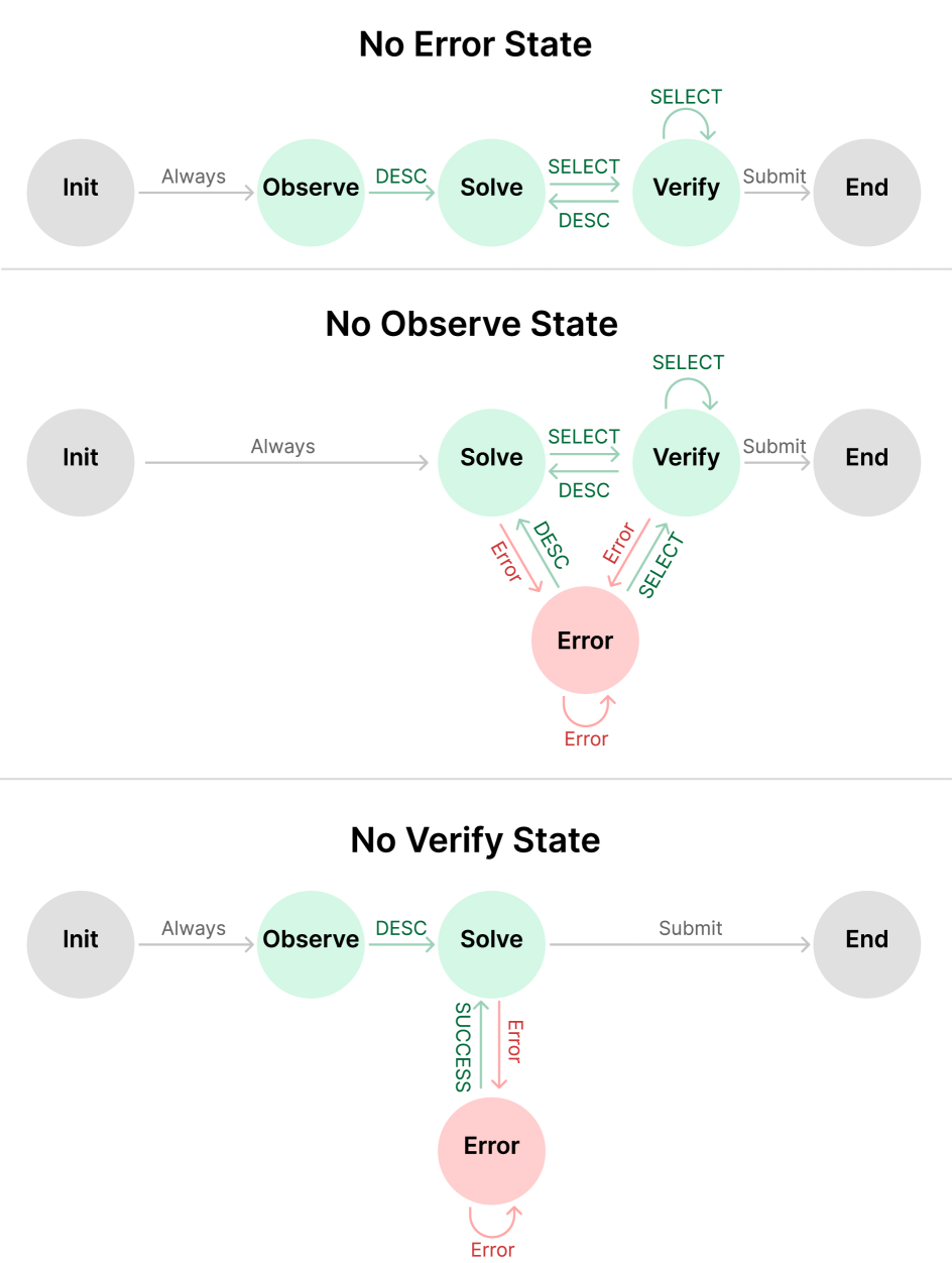
The image presents a state transition diagram divided into three distinct sections, each representing a different operational state: **No Error State**, **No Observe State**, and **No Verify State**. The diagram uses colored nodes (gray, green, pink) and labeled arrows to depict transitions between states.
---
## Section 1: No Error State
### Diagram Structure
1. **States**:
- **Init** (Gray Circle): Starting point.
- **Observe** (Green Circle): Always transitioned to from Init.
- **Solve** (Green Circle): Transitioned to from Observe via `DESC`.
- **Verify** (Green Circle): Transitioned to from Solve via `SELECT` or `DESC`.
- **End** (Gray Circle): Final state, reached from Verify via `Submit`.
2. **Transitions**:
- **Init → Observe**: Labeled `Always`.
- **Observe → Solve**: Labeled `DESC`.
- **Solve → Verify**: Bidirectional arrows labeled `SELECT` (top) and `DESC` (bottom).
- **Verify → End**: Labeled `Submit`.
- **Verify Self-Loop**: Arrows labeled `SELECT` (looping back to Verify).
### Key Observations
- The `DESC` label appears on multiple transitions, suggesting a conditional or iterative process.
- The `SELECT` label is used for both forward and backward transitions between Solve and Verify.
---
## Section 2: No Observe State
### Diagram Structure
1. **States**:
- **Init** (Gray Circle): Starting point.
- **Solve** (Green Circle): Transitioned to from Init via `Always`.
- **Verify** (Green Circle): Transitioned to from Solve via `SELECT` or `DESC`.
- **End** (Gray Circle): Final state, reached from Verify via `Submit`.
- **Error** (Pink Circle): Error state, transitioned to from Solve or Verify via `Error`.
2. **Transitions**:
- **Init → Solve**: Labeled `Always`.
- **Solve → Verify**: Bidirectional arrows labeled `SELECT` (top) and `DESC` (bottom).
- **Verify → End**: Labeled `Submit`.
- **Verify Self-Loop**: Arrows labeled `SELECT` (looping back to Verify).
- **Error Self-Loop**: Arrows labeled `Error` (looping back to Error).
- **Solve → Error**: Labeled `Error`.
- **Verify → Error**: Labeled `Error`.
### Key Observations
- The `Error` state is reachable from both Solve and Verify, indicating failure conditions.
- The `DESC` label is reused here, potentially indicating a shared error-handling mechanism.
---
## Section 3: No Verify State
### Diagram Structure
1. **States**:
- **Init** (Gray Circle): Starting point.
- **Observe** (Green Circle): Transitioned to from Init via `Always`.
- **Solve** (Green Circle): Transitioned to from Observe via `DESC`.
- **End** (Gray Circle): Final state, reached from Solve via `Submit`.
- **Error** (Pink Circle): Error state, transitioned to from Solve via `Error`.
2. **Transitions**:
- **Init → Observe**: Labeled `Always`.
- **Observe → Solve**: Labeled `DESC`.
- **Solve → End**: Labeled `Submit`.
- **Solve → Error**: Labeled `Error`.
- **Error Self-Loop**: Arrows labeled `Error` (looping back to Error).
### Key Observations
- The `SUCCESS` label appears on the transition from Solve to End, indicating successful completion.
- The `Error` state is only reachable from Solve, suggesting a simplified error pathway.
---
## Cross-Section Analysis
- **Color Coding**:
- **Gray**: Start/End states (`Init`, `End`).
- **Green**: Active states (`Observe`, `Solve`, `Verify`).
- **Pink**: Error states (`Error`).
- **Arrow Labels**:
- `Always`: Unconditional transitions.
- `DESC`, `SELECT`, `Submit`: Conditional or action-based transitions.
- `Error`: Failure states.
- `SUCCESS`: Successful completion (only in No Verify State).
---
## Summary
The diagram illustrates three operational workflows with varying error-handling mechanisms:
1. **No Error State**: A linear flow with error recovery via `DESC`/`SELECT`.
2. **No Observe State**: Skips observation, introduces error states earlier.
3. **No Verify State**: Simplifies verification, uses `SUCCESS` for completion.
All transitions are explicitly labeled, with colors and labels consistently applied across sections.