## Timing Diagram: Clock, Command, and Data Signals
### Overview
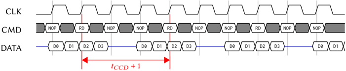
The image is a timing diagram illustrating the relationship between a clock signal (CLK), a command signal (CMD), and a data signal (DATA). The diagram shows how these signals interact over time, with specific commands (NOP, RD) and data values (D0, D1, D2, D3) being transmitted in relation to the clock signal. The diagram also indicates a time interval labeled "tCCD + 1".
### Components/Axes
* **CLK (Clock):** A square wave signal that alternates between high and low states. The clock signal provides the timing reference for the other signals.
* **CMD (Command):** A signal that represents commands being sent. The commands shown are "NOP" (No Operation) and "RD" (Read). The CMD signal alternates between gray filled boxes with the command inside and white boxes with the command inside.
* **DATA:** A signal that represents data being transmitted. The data values shown are "D0", "D1", "D2", and "D3". The DATA signal consists of white boxes with the data value inside.
* **tCCD + 1:** A red double-headed arrow indicating a time interval. The arrow spans from the rising edge of the clock signal before the "RD" command to the rising edge of the clock signal before the next "RD" command.
### Detailed Analysis
* **CLK (Clock):** The clock signal is a periodic square wave. It alternates between a high state and a low state.
* **CMD (Command):** The command signal alternates between "NOP" (No Operation) and "RD" (Read" commands. The sequence is NOP, NOP, RD, NOP, NOP, RD, NOP, NOP, RD, NOP, NOP.
* **DATA:** The data signal transmits data values D0, D1, D2, and D3. The data is transmitted when the CMD signal is "RD". When the CMD signal is "NOP", the DATA signal remains at a constant level (blue line).
* **tCCD + 1:** The time interval "tCCD + 1" represents the time between consecutive read operations.
### Key Observations
* The "RD" command is associated with the transmission of data values D0, D1, D2, and D3.
* The "NOP" command indicates no operation, and the data signal remains constant during this time.
* The clock signal provides the timing reference for the command and data signals.
### Interpretation
The timing diagram illustrates a synchronous communication protocol where commands and data are transmitted in relation to a clock signal. The "RD" command triggers the transmission of data values, while the "NOP" command indicates an idle state. The time interval "tCCD + 1" represents the cycle time between consecutive read operations. This type of diagram is used to understand and analyze the timing relationships between different signals in a digital system.