## Diagram: Data Communication Protocol Timing
### Overview
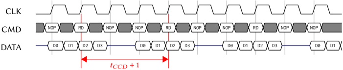
The diagram illustrates a synchronized data communication protocol with three distinct layers: a clock signal (CLK), command/data (CMD) layer, and data transmission (DATA) layer. It emphasizes timing relationships between clock cycles and data transmission events.
### Components/Axes
1. **CLK Layer**
- Topmost layer with a continuous zigzag waveform representing a clock signal.
- No explicit axis labels, but the waveform implies periodic pulses.
2. **CMD Layer**
- Middle layer with alternating gray (NOP) and white (RD) hexagonal blocks.
- Labels:
- `NOP`: No Operation (gray blocks).
- `RD`: Read (white blocks).
- Blocks are evenly spaced, aligned with CLK pulses.
3. **DATA Layer**
- Bottom layer with a continuous blue line and labeled data bits (`D0`, `D1`, `D2`, `D3`).
- Data bits repeat in a 4-bit pattern (`D0-D3`) across the timeline.
4. **Timing Arrow**
- Red arrow labeled `t_CCD + 1` spans from the first `RD` block in the CMD layer to the subsequent `RD` block.
- Indicates a timing constraint of `t_CCD + 1` clock cycles between read operations.
### Detailed Analysis
- **CLK Layer**: The zigzag waveform suggests a square wave clock signal with consistent periodicity.
- **CMD Layer**:
- `NOP` (gray) and `RD` (white) blocks alternate, with `RD` occurring every other clock cycle.
- Total visible blocks: 12 (6 `NOP`, 6 `RD`).
- **DATA Layer**:
- Data bits (`D0-D3`) repeat every 4 clock cycles, forming a cyclic pattern.
- Total visible data bits: 16 (4 repetitions of `D0-D3`).
- **Timing Relationship**:
- The `t_CCD + 1` arrow spans 2 clock cycles (from one `RD` to the next), implying a minimum delay of `t_CCD + 1` between read operations.
### Key Observations
1. **Synchronization**: The CMD and DATA layers are tightly aligned with the CLK pulses, indicating strict timing constraints.
2. **Data Pattern**: The repeating `D0-D3` sequence suggests a fixed data frame structure.
3. **Command Frequency**: `RD` operations occur at half the clock frequency (every other cycle).
4. **Timing Margin**: The `+1` in `t_CCD + 1` implies an additional clock cycle buffer for stability.
### Interpretation
This diagram models a **synchronous data transfer protocol** where:
- The clock (`CLK`) synchronizes both control commands (`NOP`, `RD`) and data transmission.
- `NOP` blocks likely serve as placeholders or padding to maintain timing alignment.
- The `t_CCD + 1` constraint ensures data is sampled correctly after a read command, accounting for propagation delays.
- The repeating `D0-D3` pattern may represent a cyclic redundancy check (CRC) or a fixed data payload format.
The protocol prioritizes timing precision, with `RD` commands triggering data capture at specific intervals. The `+1` in `t_CCD + 1` acts as a safety margin to prevent metastability in high-speed systems.