# Technical Diagram Analysis: Memory Control and DRAM Rank System
## Diagram Overview
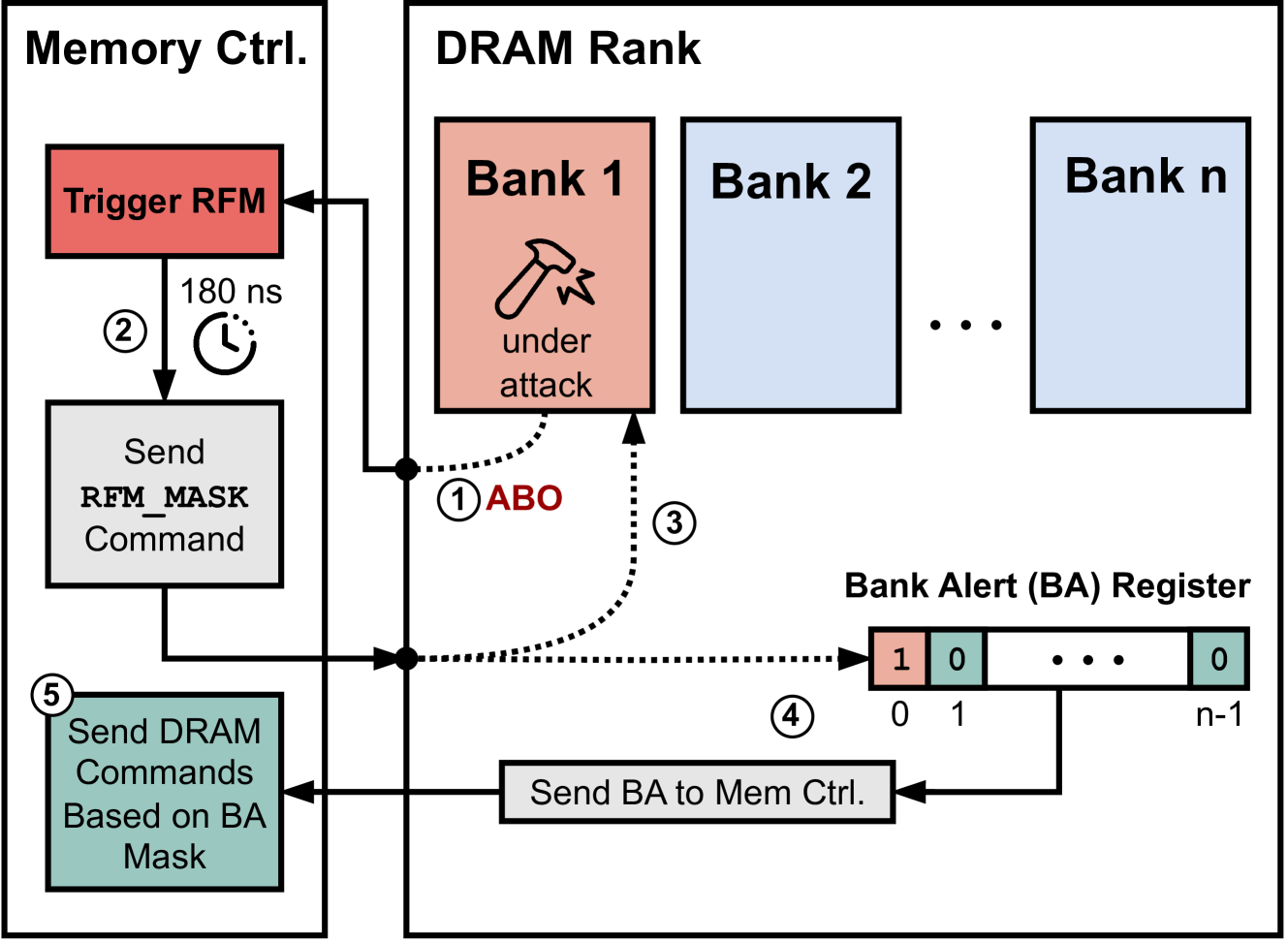
The image depicts a technical system diagram illustrating memory control operations and DRAM rank management. The diagram is divided into two primary sections: **Memory Ctrl.** (left) and **DRAM Rank** (right), with bidirectional interactions between them.
---
## Left Section: Memory Ctrl.
### Components and Flow
1. **Trigger RFM** (Red Box)
- Label: `Trigger RFM`
- Spatial Position: Top-left corner of the left section
- Connection: Arrows point to:
- `Send RFM_MASK Command` (Gray Box)
- `Send DRAM Commands Based on BA Mask` (Green Box)
2. **Send RFM_MASK Command** (Gray Box)
- Label: `Send RFM_MASK Command`
- Spatial Position: Directly below `Trigger RFM`
- Connection: Arrows point to:
- `Bank Alert (BA) Register` (Right Section)
- `Send DRAM Commands Based on BA Mask` (Green Box)
3. **Send DRAM Commands Based on BA Mask** (Green Box)
- Label: `Send DRAM Commands Based on BA Mask`
- Spatial Position: Bottom-left corner of the left section
- Connection: Arrows point to:
- `Send BA to Mem Ctrl.` (Gray Box, Right Section)
### Timing Information
- **180 ns Delay**: Indicated between `Trigger RFM` and `Send RFM_MASK Command` with a clock icon.
---
## Right Section: DRAM Rank
### Components and Flow
1. **Bank 1** (Highlighted in Red)
- Label: `Bank 1`
- Icon: Hammer with lightning bolts (symbolizing "under attack")
- Spatial Position: First bank in the sequence
- Connection: Arrows point to:
- `Bank Alert (BA) Register` (Right Section)
2. **Bank 2 to Bank n** (Light Blue Boxes)
- Labels: `Bank 2`, `Bank n`
- Spatial Position: Middle and rightmost banks
- Connection: No direct arrows; part of the DRAM rank array.
3. **Bank Alert (BA) Register** (Binary Sequence)
- Label: `Bank Alert (BA) Register`
- Binary Values: `1 0 ... 0` (with `n-1` as the last index)
- Spatial Position: Right side of the diagram
- Connection: Arrows point to:
- `Send BA to Mem Ctrl.` (Gray Box, Right Section)
4. **Send BA to Mem Ctrl.** (Gray Box)
- Label: `Send BA to Mem Ctrl.`
- Spatial Position: Bottom-center of the right section
- Connection: Arrows point to:
- `Send DRAM Commands Based on BA Mask` (Left Section)
---
## Step-by-Step Process (Numbered Labels)
1. **ABO** (Step 1)
- Label: `ABO` (Red text)
- Connection: Dotted arrow from `Bank 1` to `Bank Alert (BA) Register`
2. **180 ns Delay** (Step 2)
- Label: `180 ns`
- Connection: Between `Trigger RFM` and `Send RFM_MASK Command`
3. **Bank Alert (BA) Register** (Step 3)
- Label: `Bank Alert (BA) Register`
- Binary Sequence: `1 0 ... 0`
4. **Send BA to Mem Ctrl.** (Step 4)
- Label: `Send BA to Mem Ctrl.`
- Connection: From `Bank Alert (BA) Register` to `Send DRAM Commands Based on BA Mask`
5. **Send DRAM Commands Based on BA Mask** (Step 5)
- Label: `Send DRAM Commands Based on BA Mask`
- Connection: From `Send BA to Mem Ctrl.` back to `Memory Ctrl.`
---
## Color Coding and Legend
- **Red**: Indicates critical components (`Trigger RFM`, `Bank 1` under attack).
- **Gray**: Represents command/control operations (`Send RFM_MASK Command`, `Send BA to Mem Ctrl.`).
- **Green**: Denotes actions based on Bank Alert (`Send DRAM Commands Based on BA Mask`).
- **Light Blue**: Neutral DRAM banks (`Bank 2` to `Bank n`).
---
## Key Trends and Data Points
- **Attack Simulation**: `Bank 1` is explicitly marked as "under attack" with a hammer icon, suggesting a focus on security or fault tolerance.
- **Binary Alert System**: The `Bank Alert (BA) Register` uses a binary sequence (`1 0 ... 0`) to indicate active alerts, with only the first bank (`Bank 1`) flagged.
- **Cyclic Interaction**: The system forms a closed loop between `Memory Ctrl.` and `DRAM Rank`, with timing constraints (180 ns) ensuring synchronization.
---
## Spatial Grounding
- **Legend Colors**:
- Red: `Trigger RFM`, `Bank 1`
- Gray: `Send RFM_MASK Command`, `Send BA to Mem Ctrl.`
- Green: `Send DRAM Commands Based on BA Mask`
- Light Blue: `Bank 2` to `Bank n`
- **Binary Sequence**: `1 0 ... 0` in the `Bank Alert (BA) Register` indicates a single active alert (Bank 1).
---
## Conclusion
This diagram outlines a memory control system that detects attacks on DRAM banks (specifically Bank 1), generates alerts via a binary register, and dynamically adjusts DRAM commands based on the Bank Alert Mask (BA Mask). The 180 ns delay ensures precise timing for command execution.