\n
## Diagram: Parallel ALU Structure
### Overview
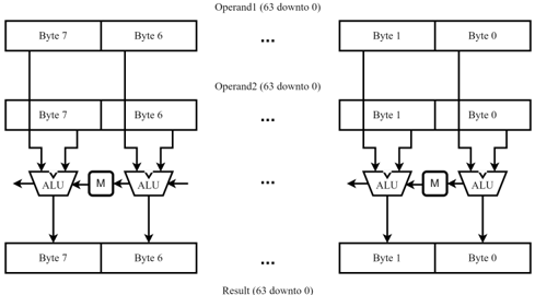
The image depicts a diagram illustrating a parallel Arithmetic Logic Unit (ALU) structure for processing 64-bit operands. The diagram shows two identical parallel processing blocks, repeated multiple times (indicated by "..."), suggesting a wider data path. Each block operates on individual bytes of the operands.
### Components/Axes
The diagram consists of the following components:
* **Operand 1 (63 downto 0):** The first input operand, represented as a series of 8 bytes (Byte 7 to Byte 0).
* **Operand 2 (63 downto 0):** The second input operand, also represented as a series of 8 bytes (Byte 1 to Byte 0).
* **ALU:** Arithmetic Logic Unit, performing the actual computation.
* **M:** Multiplier (or potentially other logic).
* **Result (63 downto 0):** The output of the parallel ALU structure, represented as a series of 8 bytes (Byte 7 to Byte 0).
* **Bytes:** Each operand and the result are divided into 8 bytes, labeled Byte 7 through Byte 0.
### Detailed Analysis or Content Details
The diagram shows a parallel structure where each byte of Operand 1 is paired with the corresponding byte of Operand 2. Each pair is fed into an ALU and a multiplier (M). The outputs of these ALUs and multipliers are then combined to form the Result.
The diagram shows two complete blocks, and then "..." indicating that this pattern repeats. The byte ordering is reversed between the two complete blocks shown. Operand 1 is shown as Byte 7 to Byte 0, while Operand 2 is shown as Byte 1 to Byte 0. The Result is shown as Byte 7 to Byte 0.
The diagram does not provide specific numerical values or operational details of the ALUs or multipliers. It only illustrates the data flow and parallel structure.
### Key Observations
* **Parallelism:** The diagram highlights a parallel processing approach, where multiple ALUs operate simultaneously on different bytes of the operands.
* **Byte-Level Operation:** The processing is performed at the byte level, suggesting that the ALU and multiplier are designed to handle 8-bit inputs.
* **Replication:** The "..." indicates that the parallel structure is replicated to handle the entire 64-bit operand.
* **Operand Ordering:** The byte ordering of Operand 1 and Operand 2 is different, which may indicate a specific data representation or processing requirement.
### Interpretation
This diagram illustrates a common technique for accelerating arithmetic and logical operations by leveraging parallelism. By dividing the operands into bytes and processing them concurrently using multiple ALUs, the overall computation time can be significantly reduced. The inclusion of a multiplier (M) suggests that the ALU structure is capable of performing multiplication as well as other arithmetic and logical operations. The byte ordering difference between Operand 1 and Operand 2 could be related to endianness or a specific data format. The diagram is a high-level representation and does not provide details about the internal workings of the ALUs or the method for combining the results from the parallel blocks. It is a conceptual illustration of a parallel processing architecture.