## Diagram: Quantum Optical Measurement and Feedback System
### Overview
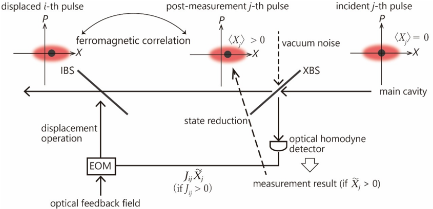
The image is a technical schematic diagram illustrating a quantum optical system involving pulse measurement, state reduction, and feedback. It depicts the transformation of optical pulses in phase space (P-X coordinates) through a series of optical components and a measurement-based feedback loop. The system appears designed to create or utilize correlations between pulses.
### Components/Axes
**Phase Space Plots (Top Row):**
* Three plots, each with horizontal axis **X** and vertical axis **P**.
* **Left Plot:** Labeled "displaced i-th pulse". Shows a red, elliptical Gaussian distribution centered at a point with positive X and P values (approximately X>0, P>0).
* **Center Plot:** Labeled "post-measurement j-th pulse". Shows a similar red elliptical distribution, but centered at a point with a larger positive X value. An annotation states **⟨X_j⟩ > 0**.
* **Right Plot:** Labeled "incident j-th pulse". Shows a red elliptical distribution centered at the origin (X=0, P=0). An annotation states **⟨X_j⟩ = 0**.
* A curved, double-headed arrow labeled **"ferromagnetic correlation"** connects the "displaced i-th pulse" and the "post-measurement j-th pulse".
**Optical Path and Components (Middle/Bottom):**
* A horizontal line represents the **"main cavity"** axis.
* **IBS:** A beam splitter (diagonal line) on the main cavity path, interacting with the "displaced i-th pulse".
* **XBS:** A second beam splitter (diagonal line) on the main cavity path, interacting with the "incident j-th pulse".
* **"vacuum noise"**: Indicated by a dashed vertical arrow pointing down onto the XBS.
* **"state reduction"**: A dashed arrow points from the XBS towards the "post-measurement j-th pulse" plot, indicating the measurement process collapses the state.
* **"optical homodyne detector"**: A detector symbol connected to the output of the XBS. A large downward arrow points from it, labeled **"measurement result (if X̃_j > 0)"**.
* **EOM (Electro-Optic Modulator):** A box receiving input from an **"optical feedback field"** (upward arrow). Its output is a **"displacement operation"** (upward arrow) applied to the IBS.
* **Feedback Path:** A line connects the output of the optical homodyne detector to the EOM. It is labeled with the mathematical condition: **J_ij X̃_j (if J_ij > 0)**.
### Detailed Analysis
The diagram describes a sequential process:
1. An **"incident j-th pulse"** (in a vacuum or coherent state centered at ⟨X_j⟩=0) enters the main cavity and interacts with beam splitter **XBS**.
2. This interaction is subject to **"vacuum noise"**.
3. The output from the XBS is measured by an **"optical homodyne detector"**, yielding a measurement result **X̃_j**.
4. If the measurement result **X̃_j > 0**, it triggers a **"state reduction"**, resulting in a **"post-measurement j-th pulse"** with a positive displacement (⟨X_j⟩ > 0).
5. The measurement result is fed back through a gain factor **J_ij** (where J_ij > 0) to an **EOM**.
6. The EOM applies a **"displacement operation"** to a separate **"displaced i-th pulse"** via beam splitter **IBS**. This operation is driven by an **"optical feedback field"**.
7. The diagram asserts a **"ferromagnetic correlation"** between the final state of the "displaced i-th pulse" and the "post-measurement j-th pulse".
### Key Observations
* **State Transformation:** The core process is the transformation of the j-th pulse from a zero-mean state (⟨X_j⟩=0) to a displaced state (⟨X_j⟩>0) via measurement and state reduction.
* **Feedback Mechanism:** The system implements a closed-loop feedback where the measurement outcome of one pulse (j) directly influences the displacement operation on another pulse (i).
* **Correlation Creation:** The label "ferromagnetic correlation" suggests the feedback is designed to create a positive correlation between the quadrature displacements of the i-th and j-th pulses.
* **Conditional Logic:** The feedback and the state reduction are explicitly conditional on the measurement result **X̃_j > 0** and the coupling constant **J_ij > 0**.
### Interpretation
This diagram represents a scheme for **measurement-induced state preparation and correlation engineering** in quantum optics. The "ferromagnetic correlation" terminology is borrowed from condensed matter physics, implying the feedback aims to align the displacements of different pulses, analogous to aligning spins in a ferromagnet.
The system demonstrates how a **projective measurement** (homodyne detection) can be used not just to read out information, but to actively prepare a desired quantum state (the displaced j-th pulse). Furthermore, it shows how this measurement result can be used as a **control signal** in a feedback loop to modulate another part of the system (the i-th pulse), thereby creating a designed correlation between two otherwise separate optical modes. This is a foundational concept in quantum control and quantum information processing, where measurement and feedback are used to combat decoherence or generate entangled states. The inclusion of "vacuum noise" acknowledges the fundamental quantum noise limit that the measurement and feedback process must contend with.