## Neural Network and Chip Implementation Analysis
### Overview
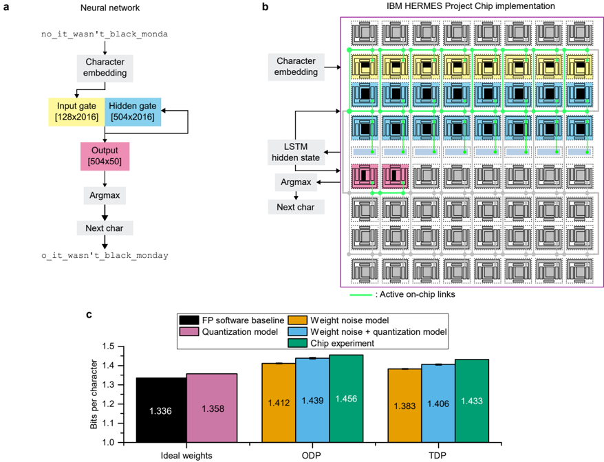
The image presents a comparison of a neural network architecture, its implementation on an IBM HERMES project chip, and a performance analysis of different models. It includes a diagram of the neural network, a schematic of the chip implementation, and a bar graph comparing the bits per character for different models under varying conditions.
### Components/Axes
**Section A: Neural Network Diagram**
* **Title:** Neural network
* **Nodes:**
* no_it_wasn't_black_monda (Input)
* Character embedding
* Input gate [128x2016] (Yellow)
* Hidden gate [504x2016] (Blue)
* Output [504x50] (Pink)
* Argmax
* Next char
* o_it_wasn't_black_monday (Output)
* **Flow:** The diagram illustrates a sequential flow: Input string -> Character embedding -> Input gate & Hidden gate (with feedback loop from Hidden gate to itself) -> Output -> Argmax -> Next char -> Output string.
**Section B: IBM HERMES Project Chip Implementation**
* **Title:** IBM HERMES Project Chip implementation
* **Components:**
* Character embedding
* LSTM hidden state
* Argmax
* Next char
* Array of chip components arranged in a grid (7x7).
* Active on-chip links (Green lines connecting chip components)
* **Color Coding:**
* Yellow: Input gate
* Blue: Hidden gate
* Pink: Output
* Grey: Inactive chip components
* Green: Active on-chip links
**Section C: Bar Graph**
* **Title:** None explicitly given, but implied as performance comparison.
* **Y-axis:** Bits per character, ranging from 1.0 to 1.5 in increments of 0.1.
* **X-axis:** Categories: Ideal weights, ODP, TDP
* **Legend:** (Position: top-right)
* Black: FP software baseline
* Pink: Quantization model
* Orange: Weight noise model
* Blue: Weight noise + quantization model
* Green: Chip experiment
### Detailed Analysis
**Section A: Neural Network Diagram**
* The diagram shows a basic neural network architecture for character generation.
* The input "no_it_wasn't_black_monda" is processed through character embedding, then passed through input and hidden gates. The hidden gate has a recurrent connection.
* The output layer produces a [504x50] matrix, which is then processed by an Argmax function to predict the next character.
**Section B: IBM HERMES Project Chip Implementation**
* The diagram illustrates how the neural network might be implemented on a chip.
* The chip consists of an array of processing units, with active links connecting specific units.
* The color-coding indicates which parts of the neural network are implemented on which chip components.
* The top rows of chips are colored yellow and blue, corresponding to the Input and Hidden gates. The row below is colored pink, corresponding to the Output.
**Section C: Bar Graph**
* **Ideal weights:**
* FP software baseline (Black): 1.336
* Quantization model (Pink): 1.358
* **ODP:**
* Weight noise model (Orange): 1.412
* Weight noise + quantization model (Blue): 1.439
* Chip experiment (Green): 1.456
* **TDP:**
* Weight noise model (Orange): 1.383
* Weight noise + quantization model (Blue): 1.406
* Chip experiment (Green): 1.433
* **Trends:**
* For Ideal weights, the quantization model performs slightly worse than the FP software baseline.
* For ODP and TDP, the chip experiment consistently shows the highest bits per character.
* Weight noise + quantization model is always higher than the weight noise model.
### Key Observations
* The chip implementation seems to be focused on the Input, Hidden, and Output gates of the neural network.
* The bar graph suggests that the chip experiment performs comparably to the software models, with some variations depending on the conditions (ODP vs. TDP).
* The quantization model has a small impact on performance compared to the FP software baseline for ideal weights.
### Interpretation
The image provides a high-level overview of a neural network implementation on a specialized chip. The neural network diagram outlines the basic architecture, while the chip implementation diagram shows how the network's components are mapped onto the chip's processing units. The bar graph offers a quantitative comparison of different models under varying conditions, suggesting that the chip implementation is a viable alternative to software-based models. The data indicates that the chip experiment achieves competitive performance, particularly under ODP and TDP conditions, suggesting potential benefits in specific operational scenarios. The use of quantization models appears to have a relatively minor impact on performance in the ideal weights scenario.