## Diagram: State Transition Network with Inverse and Y-Junction
### Overview
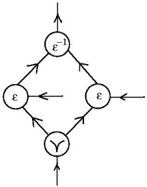
The diagram depicts a directed graph with four nodes connected by arrows, forming a network with cyclic and acyclic paths. Key elements include three nodes labeled **ε**, one node labeled **ε⁻¹**, and a Y-shaped node labeled **Y**. Arrows indicate directional relationships between nodes.
### Components/Axes
- **Nodes**:
- Top node: **ε⁻¹** (inverse of ε).
- Right node: **ε**.
- Left node: **ε**.
- Bottom node: **Y** (Y-shaped symbol).
- **Arrows**:
- **ε⁻¹ → ε** (top to right).
- **ε → Y** (right to bottom).
- **ε → Y** (left to bottom).
- **Y → ε** (bottom to left).
- **Y → ε** (bottom to right).
- **ε → ε** (left to right, horizontal).
### Detailed Analysis
- **Node Labels**:
- Three nodes are labeled **ε** (standard symbol, possibly representing a unit or identity element).
- One node is labeled **ε⁻¹** (inverse of ε, suggesting a reverse operation or starting point).
- The Y-shaped node is unlabeled but distinct in shape, acting as a junction.
- **Flow Directions**:
- The **ε⁻¹** node initiates a path to the right **ε** node.
- Both **ε** nodes (left and right) connect to the **Y** node.
- The **Y** node splits into two outgoing arrows, feeding back into the left and right **ε** nodes.
- A horizontal arrow connects the left **ε** node to the right **ε** node.
### Key Observations
1. **Cyclic Paths**:
- The **Y** node forms a loop with both **ε** nodes (left and right), creating bidirectional dependencies.
2. **Inverse Element**:
- The **ε⁻¹** node suggests an initial or reverse state, contrasting with the standard **ε** nodes.
3. **Y-Junction Behavior**:
- The **Y** node acts as a central hub, merging inputs from both **ε** nodes and distributing outputs back to them.
### Interpretation
This diagram likely represents a **state transition system** or **process flow** with the following implications:
- **Mathematical Context**: If **ε** represents a generator in group theory, **ε⁻¹** could denote its inverse, and the **Y** node might symbolize a relation or constraint (e.g., commutativity).
- **Process Workflow**: The **Y** node could represent a decision point where paths diverge or converge, with feedback loops enabling iterative processes.
- **Anomalies**: The horizontal arrow between **ε** nodes (left to right) introduces a direct connection outside the **Y**-mediated cycles, potentially signifying a shortcut or alternative pathway.
The structure emphasizes interdependence between nodes, with the **Y** node central to maintaining balance between cyclic and acyclic transitions. The presence of **ε⁻¹** highlights asymmetry in the system’s initialization or termination states.