## Flowchart: Multi-Stage Octree Processing Pipeline
### Overview
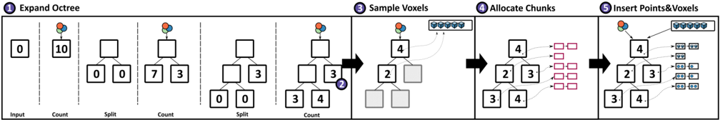
The image depicts a hierarchical, multi-stage algorithm for processing 3D spatial data using octree decomposition and voxel allocation. The flowchart progresses left-to-right through five distinct phases, with branching logic and data transformations at each step. Color-coded elements (red, blue, green circles; red/blue boxes) represent different data types or processing states.
### Components/Axes
1. **Phases** (Left-to-Right Flow):
- Phase 1: Expand Octree
- Phase 2: Sample Voxels
- Phase 3: Allocate Chunks
- Phase 4: Insert Points&Voxels
2. **Key Elements**:
- **Input**: Single "0" value
- **Count Operations**: Numeric values (10, 7, 3, 4, 2, 3, 4)
- **Split Operations**: Binary/ternary divisions (0→0,0; 7→3,4; 3→2,4)
- **Voxel Representation**: Blue cubes (6 total)
- **Chunk Allocation**: Red/blue boxes (12 total)
- **Color-Coded Elements**:
- Red circles: Likely root nodes
- Blue circles: Leaf nodes
- Green circles: Intermediate nodes
- Red boxes: Processed chunks
- Blue boxes: Raw voxels
### Detailed Analysis
1. **Phase 1: Expand Octree**
- Input: Single "0" value
- Count: 10 (root node expansion)
- Split: 0→0,0 (binary split)
- Subsequent splits: 7→3,4; 3→2,4; 4→3,4
2. **Phase 2: Sample Voxels**
- Input: 4 (from Phase 1)
- Output: 6 blue cubes (voxel sampling)
3. **Phase 3: Allocate Chunks**
- Input: 4 (from Phase 2)
- Output: 12 boxes (6 red + 6 blue)
- Allocation pattern: 4→2,3→3,4
4. **Phase 4: Insert Points&Voxels**
- Final output: 12 boxes with embedded blue cubes
- Color consistency: Blue boxes retain original voxel data
### Key Observations
1. **Hierarchical Decomposition**: Each split operation reduces node size by factors of 2-4
2. **Data Flow**: Input value 0→10→7→3→4→2→3→4 through successive splits
3. **Memory Allocation**: 1:2 ratio of red (processed) to blue (raw) boxes
4. **Color Consistency**: Blue cubes maintain identity through all phases
5. **Branching Logic**: Each split creates two/three child nodes
### Interpretation
This flowchart represents a 3D spatial data processing pipeline with octree-based hierarchical decomposition. The process begins with a single root node (0) that expands through recursive splitting (Phase 1), samples voxels at leaf nodes (Phase 2), allocates memory chunks for storage (Phase 3), and finally inserts processed data into the structure (Phase 4). The consistent use of blue cubes suggests voxel data persistence through transformations, while red boxes indicate processed/optimized data segments. The algorithm appears designed for efficient 3D data management, possibly for applications like 3D rendering, scientific visualization, or spatial database indexing. The color-coding system provides visual cues for data state transitions, with green nodes acting as transitional states between root (red) and leaf (blue) nodes.