## Diagram: Triangle Configurations
### Overview
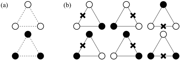
The image shows two sets of triangle configurations, labeled (a) and (b). Each triangle has vertices represented by circles, which are either filled (black) or unfilled (white). In set (a), there are two triangles, one with all white vertices and one with all black vertices. In set (b), there are six triangles, each with a mix of black and white vertices, and each containing an "X" mark near one of the vertices.
### Components/Axes
* **Vertices:** Represented by circles, either filled (black) or unfilled (white).
* **Edges:** Represented by solid lines connecting the vertices.
* **Dashed Lines:** In diagram (a), dashed lines connect the vertices of each triangle.
* **"X" Marks:** Present in all triangles in diagram (b), located near one of the vertices.
* **Labels:** (a) and (b) identify the two sets of configurations.
### Detailed Analysis or ### Content Details
**Diagram (a):**
* **Top Triangle:** All three vertices are unfilled (white). The edges are dashed.
* **Bottom Triangle:** All three vertices are filled (black). The edges are dashed.
**Diagram (b):**
There are six triangles, arranged in two rows of three. Each triangle has two vertices of one color and one vertex of the other color. Each triangle also has an "X" mark near one of the vertices.
* **Top Row, Left Triangle:** Top vertex is white with an "X" mark. Bottom-left vertex is white. Bottom-right vertex is black.
* **Top Row, Middle Triangle:** Top vertex is white. Bottom-left vertex is black. Bottom-right vertex is white with an "X" mark.
* **Top Row, Right Triangle:** Top vertex is black. Bottom-left vertex is white. Bottom-right vertex is white with an "X" mark.
* **Bottom Row, Left Triangle:** Top vertex is black with an "X" mark. Bottom-left vertex is white. Bottom-right vertex is black.
* **Bottom Row, Middle Triangle:** Top vertex is black. Bottom-left vertex is black with an "X" mark. Bottom-right vertex is white.
* **Bottom Row, Right Triangle:** Top vertex is white. Bottom-left vertex is black. Bottom-right vertex is black with an "X" mark.
### Key Observations
* Diagram (a) shows two extreme configurations: all vertices white and all vertices black.
* Diagram (b) shows all possible configurations with two vertices of one color and one vertex of the other color, along with an "X" mark near each vertex.
* The "X" mark appears to be associated with a specific vertex in each triangle in diagram (b).
### Interpretation
The image likely represents different states or configurations of a system with three components. The filled and unfilled circles could represent two different states of each component. Diagram (a) shows the two homogeneous states, while diagram (b) shows the heterogeneous states. The "X" mark might indicate a specific property or modification of the vertex it is near. The dashed lines in diagram (a) might indicate a weaker or different type of connection compared to the solid lines in diagram (b). Without further context, it's difficult to determine the exact meaning of these configurations.