## Process Flow Diagram: Rule Verification Engine
### Overview
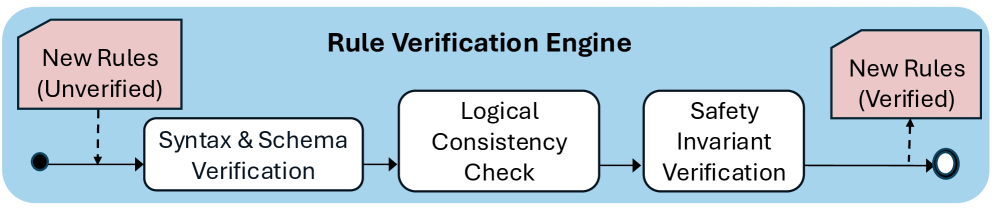
The image displays a linear workflow diagram titled "Rule Verification Engine." It illustrates the lifecycle of a rule, starting from an unverified state, passing through three distinct verification stages, and concluding as a verified rule. The entire process is contained within a light blue rounded rectangular background.
### Components/Axes
The diagram is organized horizontally from left to right.
* **Header/Title:** "Rule Verification Engine" (centered at the top).
* **Input Component (Top-Left):** A pink, document-shaped box labeled "New Rules (Unverified)."
* **Start Node:** A solid black circle located on the far left of the main flow line.
* **Process Steps (Main Flow, Left to Right):**
1. **Syntax & Schema Verification:** A white rectangular box.
2. **Logical Consistency Check:** A white rectangular box.
3. **Safety Invariant Verification:** A white rectangular box.
* **Output Component (Top-Right):** A pink, document-shaped box labeled "New Rules (Verified)."
* **End Node:** A hollow circle located on the far right of the main flow line.
* **Connectors:**
* **Solid lines with arrows:** Indicate the primary left-to-right progression of the process.
* **Dashed lines with arrows:** Indicate the injection of input data (from the unverified box) and the extraction of output data (to the verified box).
### Detailed Analysis
The process flow follows a sequential, unidirectional path:
1. **Initialization:** The process begins at the solid black circle.
2. **Input Injection:** A dashed arrow points from the "New Rules (Unverified)" box to the main flow line, immediately following the start node.
3. **Stage 1 (Syntax & Schema Verification):** The flow enters the first white box. This stage likely validates the structural integrity and formatting of the rules.
4. **Stage 2 (Logical Consistency Check):** The flow proceeds to the second white box. This stage likely validates the semantic correctness or logical soundness of the rules.
5. **Stage 3 (Safety Invariant Verification):** The flow proceeds to the final white box. This stage likely validates that the rules adhere to predefined safety constraints.
6. **Output Extraction:** A dashed arrow points from the main flow line (after the final verification step) to the "New Rules (Verified)" box.
7. **Termination:** The process concludes at the hollow circle on the far right.
### Key Observations
* **Linearity:** The diagram represents a "happy path" workflow. There are no visible feedback loops, error-handling branches, or rejection paths shown.
* **Color Coding:** The use of pink for the input/output states and white for the processing steps creates a clear visual distinction between data states and functional operations.
* **Hierarchy of Verification:** The placement of "Safety Invariant Verification" as the final step suggests it is the most critical or perhaps the most computationally intensive check, performed only after the rule has passed structural and logical validation.
### Interpretation
This diagram represents a high-level architectural abstraction of a rule-processing pipeline.
* **Functional Logic:** The engine acts as a filter. By placing "Syntax & Schema" first, the system ensures that only well-formed data reaches the more complex "Logical" and "Safety" checks, optimizing computational resources.
* **Safety-Critical Design:** The inclusion of a specific "Safety Invariant Verification" step implies that this engine is likely used in a high-stakes environment (such as industrial control systems, autonomous vehicle logic, or financial compliance) where rule correctness is not just about logic, but about preventing catastrophic outcomes.
* **Missing Information:** As a "happy path" diagram, it omits the "what happens if it fails" scenario. In a real-world implementation, there would necessarily be exit points or error-handling branches from each of the three verification boxes to handle invalid rules. The absence of these suggests this is a conceptual model rather than a complete system architecture diagram.