## Flowchart: Rule Verification Engine
### Overview
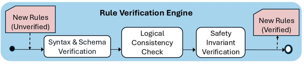
The image depicts a flowchart illustrating the process of verifying new rules through a multi-stage verification engine. The workflow begins with "New Rules (Unverified)" and progresses through three verification stages before becoming "New Rules (Verified)."
### Components/Axes
- **Title**: "Rule Verification Engine" (centered at the top).
- **Input**: "New Rules (Unverified)" (pink rectangle, top-left).
- **Output**: "New Rules (Verified)" (pink rectangle, top-right).
- **Verification Stages**:
1. **Syntax & Schema Verification** (white rectangle, left-center).
2. **Logical Consistency Check** (white rectangle, center).
3. **Safety Invariant Verification** (white rectangle, right-center).
- **Arrows**: Black arrows connect the stages sequentially.
- **Circles**: Black circles at the start (input) and end (output) of the workflow.
### Detailed Analysis
- **Textual Labels**:
- All labels are in English.
- No non-English text is present.
- **Flow Direction**: Left-to-right progression from unverified to verified rules.
- **No Numerical Data**: The diagram contains no numerical values, trends, or quantitative metrics.
### Key Observations
- The process is strictly sequential, with no branching or feedback loops.
- Each verification stage is distinct and mandatory for rule validation.
- The use of pink rectangles for input/output emphasizes their status as rule sets.
### Interpretation
This flowchart represents a deterministic rule validation pipeline. The three verification stages ensure rules meet syntactic, logical, and safety criteria before being marked as "Verified." The absence of feedback loops suggests a linear, non-iterative process. The design prioritizes clarity in workflow stages, likely for technical documentation or system architecture diagrams.
**Note**: No numerical data or trends are present, as the image focuses on process flow rather than quantitative analysis.