## Neural Network Architecture Diagram: Skip Connection Block
### Overview
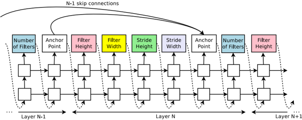
The image is a technical diagram illustrating a segment of a neural network architecture, specifically focusing on a block of layers (Layer N-1, Layer N, Layer N+1) that incorporate skip connections. The diagram uses a flowchart style with labeled parameter boxes and directional arrows to depict data flow and connectivity. The primary language is English.
### Components/Axes
The diagram is organized horizontally, representing the sequential flow of data through network layers from left to right.
**Layer Labels (Bottom):**
* `Layer N-1` (Leftmost)
* `Layer N` (Center)
* `Layer N+1` (Rightmost)
**Parameter Boxes (Top, from left to right):**
These are colored rectangular boxes, each containing a text label for a specific hyperparameter or architectural component. They are arranged in a repeating pattern across the layers.
1. **Blue Box:** `Number of Filters`
2. **Purple Box:** `Anchor Point`
3. **Pink Box:** `Filter Height`
4. **Yellow Box:** `Filter Width`
5. **Green Box:** `Stride Height`
6. **Light Purple Box:** `Stride Width`
7. **Purple Box:** `Anchor Point` (Repeated)
8. **Blue Box:** `Number of Filters` (Repeated)
9. **Pink Box:** `Filter Height` (Repeated)
**Connectivity Elements:**
* **Solid Horizontal Arrows:** Indicate the primary forward data flow between adjacent layers (e.g., from Layer N-1 to Layer N, and from Layer N to Layer N+1).
* **Dotted Curved Arrows:** Indicate internal skip connections or residual pathways *within* a single layer block (e.g., within Layer N).
* **Curved Solid Arrow (Top):** A prominent curved arrow originates from the output of the first `Anchor Point` in Layer N-1 and points to the input of the second `Anchor Point` in Layer N. It is labeled `N-1 skip connections`.
* **Square Nodes:** Small squares connected by arrows represent the processing units or operations within each layer.
### Detailed Analysis
The diagram details the internal structure of a neural network block, emphasizing parameterization and connectivity.
**Spatial Layout & Flow:**
* The overall data flow is **left-to-right**.
* The `N-1 skip connections` arrow is positioned at the **top-center** of the diagram, arching over the main layer sequence.
* The parameter boxes are aligned in a single row **above** the main processing nodes (squares).
* The layer labels (`Layer N-1`, etc.) are centered **below** their respective sections.
**Component Relationships:**
1. **Layer N-1:** Contains a sequence of processing nodes. Its output feeds into Layer N. A key output from its first `Anchor Point` is the source for the `N-1 skip connections`.
2. **Layer N:** This is the central, most detailed layer. It receives:
* The main input from Layer N-1 (via solid arrow).
* The skip connection from Layer N-1's `Anchor Point` (via the top curved arrow).
The layer processes data through its sequence of nodes, with internal dotted-line skip connections. Its output proceeds to Layer N+1.
3. **Layer N+1:** The rightmost layer shown, receiving input from Layer N. Its structure is partially visible, showing a `Number of Filters` and `Filter Height` parameter.
**Parameter Pattern:**
The sequence of parameter boxes (`Number of Filters`, `Anchor Point`, `Filter Height`, `Filter Width`, `Stride Height`, `Stride Width`) defines the configuration for a convolutional or similar operation within the layer. The repetition of `Anchor Point` and `Number of Filters` suggests these are critical junction points or that the layer may have multiple sub-blocks.
### Key Observations
1. **Explicit Skip Connection Labeling:** The diagram explicitly names and visually traces the `N-1 skip connections`, highlighting this as a core architectural feature, common in ResNet-like models to combat the vanishing gradient problem.
2. **Parameter Transparency:** Unlike abstract block diagrams, this one explicitly lists key hyperparameters (filter dimensions, stride, number of filters), making it a detailed blueprint rather than a high-level schematic.
3. **Dual Connectivity:** The diagram shows two types of skip connections: the named, long-range `N-1` connection and the shorter, internal dotted connections within Layer N.
4. **Anchor Point Emphasis:** The `Anchor Point` parameter appears twice in the sequence for Layer N, suggesting it may be a pivotal layer for feature aggregation or branching.
### Interpretation
This diagram is a **technical schematic for a deep learning model's building block**, likely a residual block or a variant thereof. It serves as a precise reference for implementation.
* **What it demonstrates:** It shows how data flows through a series of transformations (defined by filters, strides, etc.) and how information from an earlier layer (`N-1`) is directly reintroduced later (`Layer N`). This architecture enables the training of much deeper networks by providing "shortcuts" for gradient flow during backpropagation.
* **Relationships:** The elements relate hierarchically: **Layers** contain **processing sequences** defined by **hyperparameters**. The **skip connections** create cross-layer relationships that bypass the standard sequential flow.
* **Notable Anomalies/Patterns:** The most significant pattern is the **explicit, labeled skip connection from Layer N-1 to Layer N**. This is the diagram's central focus. The repetition of `Anchor Point` and `Number of Filters` within Layer N's parameter list is also notable, possibly indicating a bottleneck design or a multi-branch structure within that single layer. The diagram provides the exact "recipe" (parameters) and "wiring diagram" (connections) needed to construct this part of the neural network.