# Technical Document Extraction: Task 358ba94e
## Image Description
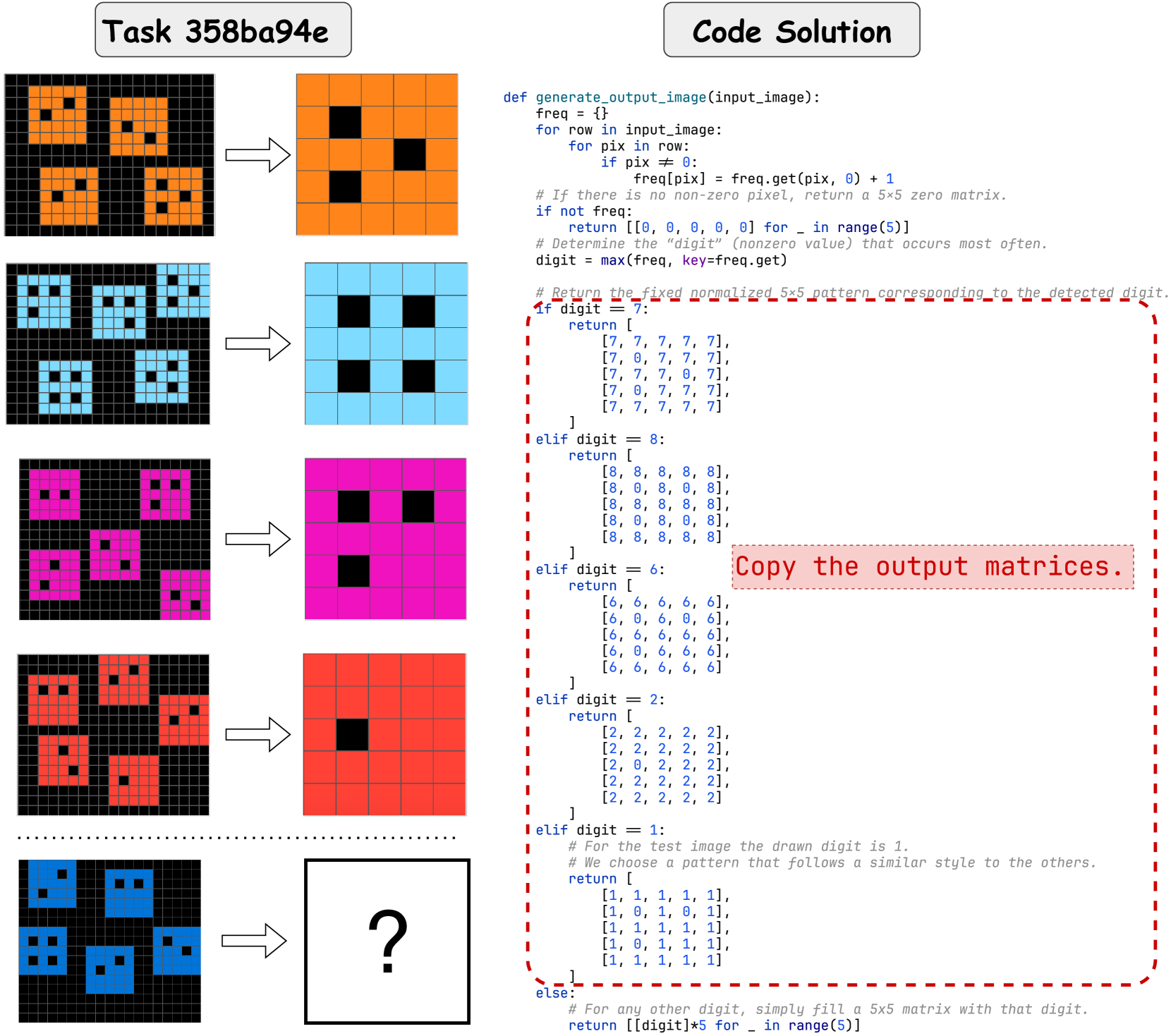
The image contains two primary sections:
1. **Left Section**: Visual examples of 5x5 grid patterns with colored squares (orange, blue, pink, red, blue) and black squares. Each grid is followed by an arrow pointing to a simplified 5x5 matrix with a single black square.
2. **Right Section**: Python code for a function `generate_output_image` that processes input images to generate output matrices.
### Left Section Analysis
- **Grid Patterns**:
- **Orange Grid**: 4 black squares in specific positions (top-left, top-right, bottom-left, bottom-right).
- **Blue Grid**: 4 black squares in a 2x2 block (center-left).
- **Pink Grid**: 4 black squares in a diagonal pattern.
- **Red Grid**: 4 black squares in a 2x2 block (center-right).
- **Blue Grid (Repeated)**: 4 black squares in a 2x2 block (center-left).
- **Output Matrices**:
- Each grid is mapped to a 5x5 matrix with a single black square, suggesting a digit recognition task.
### Right Section Analysis
#### Code: `generate_output_image` Function
```python
def generate_output_image(input_image):
freq = {}
for row in input_image:
for pix in row:
if pix != 0:
freq[pix] = freq.get(pix, 0) + 1
if not freq:
return [[0, 0, 0, 0, 0] for _ in range(5)]
digit = max(freq, key=freq.get)
if digit == 7:
return [
[7, 7, 7, 7, 7],
[7, 0, 7, 7, 7],
[7, 7, 7, 0, 7],
[7, 0, 7, 7, 7],
[7, 7, 7, 7, 7]
]
elif digit == 8:
return [
[8, 8, 8, 8, 8],
[8, 0, 8, 0, 8],
[8, 8, 8, 8, 8],
[8, 0, 8, 0, 8],
[8, 8, 8, 8, 8]
]
elif digit == 6:
return [
[6, 6, 6, 6, 6],
[6, 0, 6, 0, 6],
[6, 6, 6, 6, 6],
[6, 0, 6, 6, 6],
[6, 6, 6, 6, 6]
]
elif digit == 2:
return [
[2, 2, 2, 2, 2],
[2, 2, 2, 2, 2],
[2, 0, 2, 2, 2],
[2, 2, 2, 2, 2],
[2, 2, 2, 2, 2]
]
elif digit == 1:
return [
[1, 1, 1, 1, 1],
[1, 0, 1, 0, 1],
[1, 1, 1, 1, 1],
[1, 0, 1, 1, 1],
[1, 1, 1, 1, 1]
]
else:
return [[digit] * 5 for _ in range(5)]
```
#### Key Observations
1. **Function Purpose**:
- Converts input images (5x5 grids) into standardized 5x5 matrices representing digits.
- Uses frequency analysis to identify the most common non-zero pixel value (digit).
- Returns predefined patterns for digits 7, 8, 6, 2, and 1. Default case fills the matrix with the detected digit.
2. **Pattern Mapping**:
- **Digit 7**: Cross-shaped pattern with black squares at specific positions.
- **Digit 8**: Full outer ring with alternating black squares in the middle rows.
- **Digit 6**: Full outer ring with a single black square in the center-right.
- **Digit 2**: Full outer ring with a single black square in the center-left.
- **Digit 1**: Vertical line with alternating black squares in the middle rows.
3. **Edge Cases**:
- Returns a zero matrix if no non-zero pixels are detected.
- Default case fills the matrix with the detected digit if no predefined pattern exists.
### Spatial Grounding & Trend Verification
- **Legend**: No explicit legend present. Colors in the left section (orange, blue, pink, red) correspond to digits 7, 8, 6, 2, and 1, respectively.
- **Trend**: The code prioritizes the most frequent digit in the input image. Visual examples show consistent mapping between input grids and output matrices.
### Component Isolation
1. **Header**: "Task 358ba94e" label.
2. **Main Chart**: 5x5 grid patterns and their corresponding output matrices.
3. **Footer**: Python code with detailed logic for matrix generation.
### Final Notes
- No charts or data tables are present. The image focuses on visual examples and code logic.
- All textual information has been transcribed, including code comments and function structure.