## System Architecture Diagram: Parallel Blockchain Processing Pipeline
### Overview
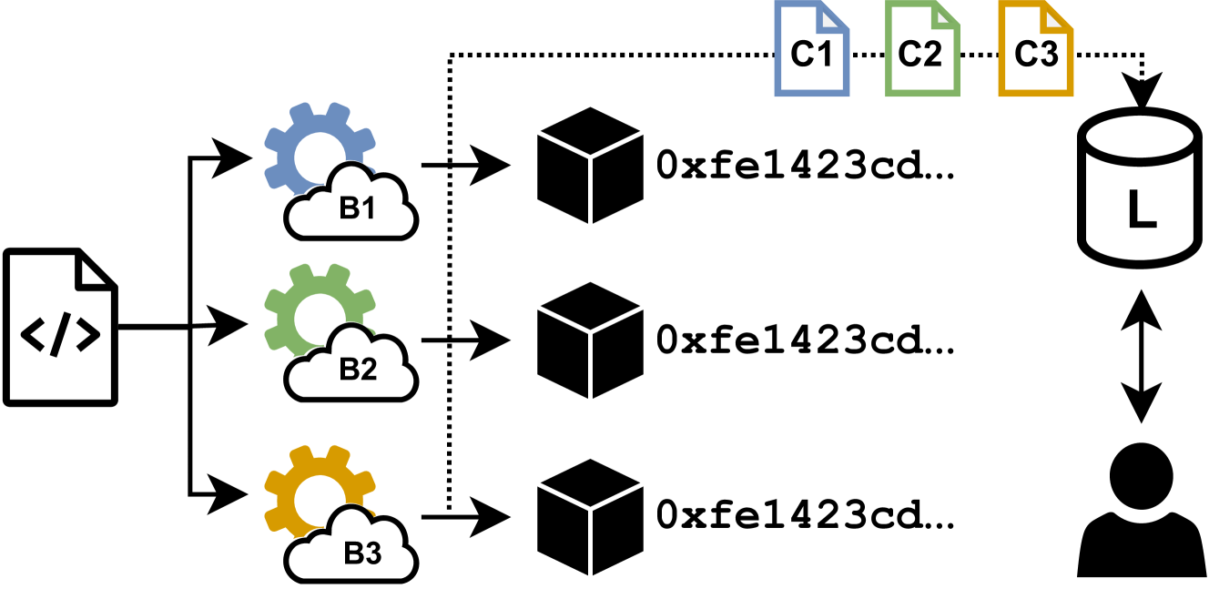
The image is a technical system architecture diagram illustrating a parallel processing workflow, likely for a blockchain or distributed ledger system. It depicts a source code file being processed by three parallel services, each generating an output that is stored in a shared ledger, which is then accessible by an end-user. The diagram uses symbolic icons and labels to represent components and data flow.
### Components/Axes
The diagram is organized into three main vertical sections from left to right:
1. **Input Section (Left):**
* A single icon representing a source code file, labeled with the symbol `</>`.
2. **Processing Section (Middle):**
* Three parallel processing paths, each consisting of:
* A **cloud-gear icon** (representing a service or compute node). These are labeled **B1** (blue), **B2** (green), and **B3** (yellow/orange).
* A **cube icon** (representing a block, transaction, or data object). Each cube is associated with the same hexadecimal address: `0xfe1423cd...`.
3. **Storage & User Section (Right):**
* A **cylinder icon** labeled **L**, representing a ledger or database.
* A **user icon** (person silhouette) below the ledger.
* Three **file icons** above the ledger, labeled **C1** (blue), **C2** (green), and **C3** (yellow/orange).
**Flow & Connections:**
* A solid arrow points from the source code file (`</>`) to each of the three cloud-gear icons (B1, B2, B3).
* Solid arrows point from each cloud-gear icon to its corresponding cube icon.
* A **dotted line** originates from the source code file, travels upward, then rightward across the top of the diagram, and terminates with an arrow pointing down into the ledger (`L`). This line passes through the three file icons (C1, C2, C3).
* A **bidirectional arrow** connects the ledger (`L`) and the user icon, indicating read/write access.
### Detailed Analysis
* **Component Labels & Text:**
* Source Code File: `</>`
* Service/Node Labels: `B1`, `B2`, `B3`
* Output Object Address: `0xfe1423cd...` (identical for all three cubes)
* Ledger Label: `L`
* File/Configuration Labels: `C1`, `C2`, `C3`
* **Color Coding & Spatial Grounding:**
* The color of the cloud-gear icon (B1=blue, B2=green, B3=yellow) matches the color of its corresponding file icon (C1=blue, C2=green, C3=yellow) located in the top-right. This establishes a direct visual link between each processing service and its associated configuration or output file.
* The three cube icons and their hex addresses are positioned vertically in the center of the diagram.
* The ledger (`L`) is positioned in the top-right quadrant. The user icon is directly below it in the bottom-right.
* **Data Flow Interpretation:**
1. A single source code artifact (`</>`) is deployed or sent to three parallel services (B1, B2, B3).
2. Each service processes the input and produces an output object (represented by the cube), all referencing the same contract or data address (`0xfe1423cd...`).
3. A separate, dotted-line flow suggests that metadata, configuration, or results (C1, C2, C3) associated with the source code are also sent to the ledger (`L`).
4. The final ledger (`L`) aggregates data from all three processing paths and is accessible to the end-user.
### Key Observations
1. **Identical Output Addresses:** All three processing paths (B1, B2, B3) produce outputs linked to the same hexadecimal address (`0xfe1423cd...`). This is a critical observation. It could indicate:
* The deployment of the same smart contract to three different nodes or shards.
* Three parallel transactions interacting with the same contract address.
* A simplification in the diagram where the address is a placeholder.
2. **Dual Data Pathways:** The diagram explicitly shows two distinct data flows from the source code: a primary processing flow (solid arrows through B1-B3) and a secondary metadata/configuration flow (dotted line through C1-C3).
3. **Color-Coded Association:** The consistent color pairing between service icons (B-series) and file icons (C-series) is a deliberate design choice to show relationship without explicit connecting lines.
4. **Centralized Ledger:** Despite parallel processing, all data converges into a single ledger (`L`), which serves as the unified interface for the user.
### Interpretation
This diagram illustrates a **scalable or fault-tolerant processing pattern** for blockchain-based applications. The core concept is distributing the workload from a single source (e.g., a dApp frontend, a contract factory) across multiple identical services (B1, B2, B3). This could represent:
* **Sharding:** Processing transactions in parallel across different shards.
* **Redundancy/Fault Tolerance:** Running the same process on multiple nodes for reliability.
* **Load Balancing:** Distributing user requests to prevent any single node from being overwhelmed.
The identical hex address (`0xfe1423cd...`) is the most significant technical detail. It strongly suggests that the system is interacting with a **single, canonical smart contract or data structure** on the ledger, even though the computation is parallelized. The services (B1-B3) are likely stateless processors or validators executing logic related to that central contract.
The dotted line with files C1-C3 represents an important ancillary process—perhaps logging, emitting events, or storing configuration artifacts—that happens independently of the main transaction flow but is crucial for auditability or system setup. The bidirectional arrow between the ledger and user confirms the system's purpose: to provide users with a consistent, aggregated view of the state managed by the distributed backend.
**In summary, the diagram depicts a pattern where a single codebase is executed in parallel by multiple services to interact with a common on-chain resource, with results and metadata aggregated into a user-accessible ledger.** The design emphasizes parallelism, a single source of truth (the ledger), and clear separation between processing and storage.