## Diagram: SR-IOV PCIe Device Architecture with SVFF
### Overview
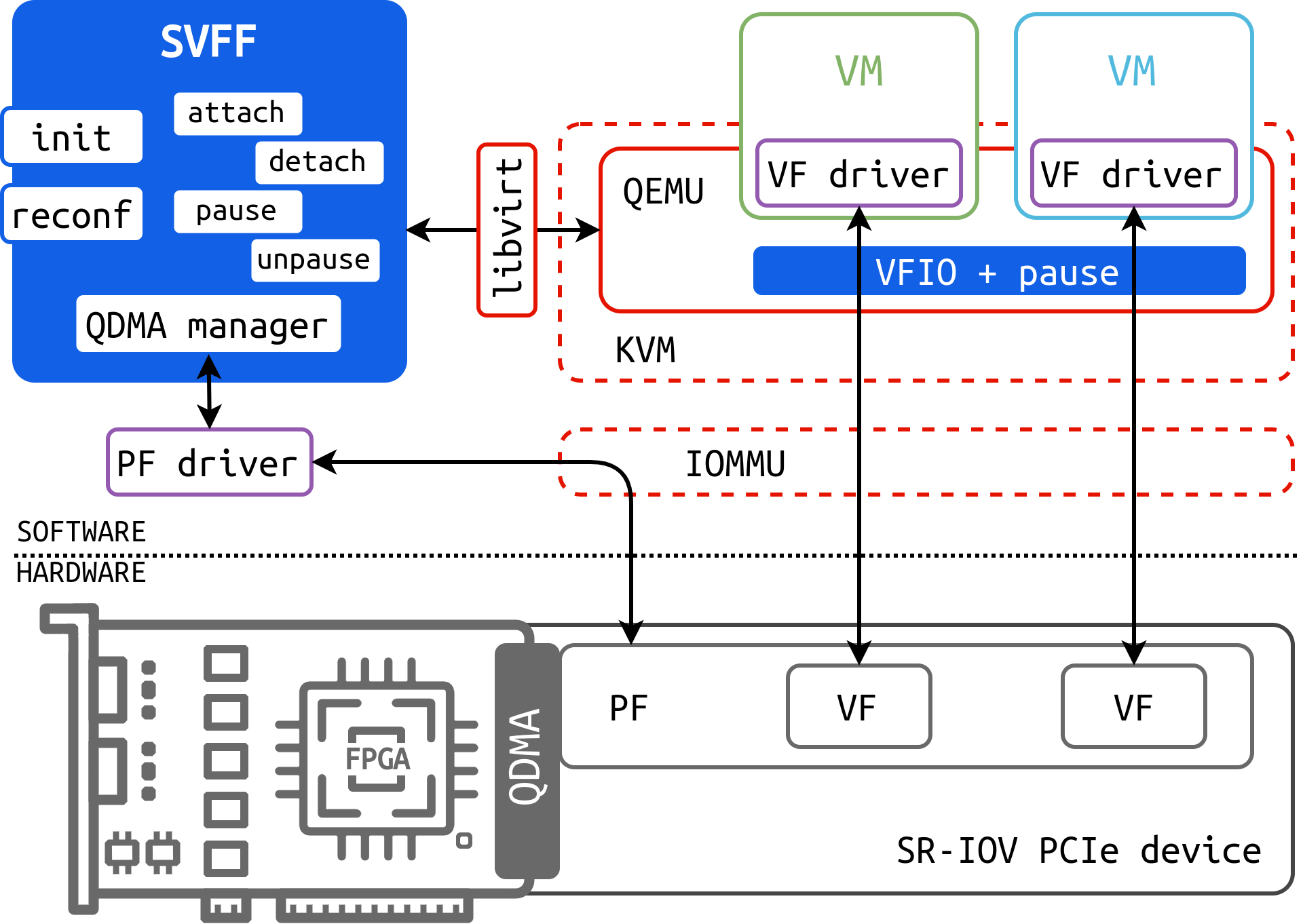
This diagram illustrates the architecture of a Single Root I/O Virtualization (SR-IOV) PCIe device, focusing on the integration of the Scalable Virtual Function Framework (SVFF). It depicts the software and hardware components involved in virtualizing access to a physical function (PF) and virtual functions (VFs) within a system, including VMs managed by QEMU/KVM. The diagram highlights the data flow and interactions between these components.
### Components/Axes
The diagram is segmented into two main areas: Software (top) and Hardware (bottom). Key components include:
* **SVFF:** A blue rectangular block with the following internal labels: "init", "attach", "detach", "pause", "unpause", "reconf".
* **QDMA Manager:** Located within the SVFF block.
* **PF driver:** Connects the SVFF to the PF.
* **libvirt:** A red rectangular block.
* **QEMU:** A light blue oval.
* **KVM:** A light blue oval.
* **VM:** Two green rectangular blocks labeled "VM", each containing a "VF driver".
* **VFIO + pause:** A blue rectangular block connecting the VMs.
* **IOMMU:** A dashed oval.
* **PF:** A dark gray block.
* **VF:** Two white blocks.
* **SR-IOV PCIe device:** A label indicating the hardware section.
* **QDMA:** A dark gray block with an internal representation of an FPGA.
* **Software/Hardware:** A label dividing the diagram.
### Detailed Analysis or Content Details
The diagram shows a layered architecture.
1. **Software Layer:**
* The SVFF, containing the QDMA manager, initiates operations like "init", "attach", "detach", "pause", "unpause", and "reconf".
* The SVFF interacts with the PF driver, which in turn connects to the PF in the hardware layer.
* libvirt manages the virtualization environment.
* QEMU and KVM provide the virtualization platform for the VMs.
* Each VM contains a VF driver, which interacts with the VF through VFIO.
* VFIO manages the pause functionality.
2. **Hardware Layer:**
* The PF and VFs reside on an SR-IOV PCIe device.
* The QDMA (with an internal FPGA) represents the physical hardware.
* The IOMMU facilitates memory management and isolation between the VMs and the hardware.
3. **Data Flow:**
* The SVFF sends commands to the QDMA manager.
* The QDMA manager interacts with the PF driver.
* The PF driver communicates with the PF.
* The PF provides access to the VFs.
* VMs access the VFs through their VF drivers and VFIO.
* libvirt interacts with QEMU/KVM to manage the VMs.
* The IOMMU provides memory isolation and virtualization support.
### Key Observations
* The diagram emphasizes the role of the SVFF in managing the SR-IOV device.
* The use of dashed lines indicates indirect or virtualized connections.
* The diagram highlights the separation between software and hardware layers.
* The inclusion of "pause" functionality suggests a mechanism for managing resource allocation or prioritizing access to the VFs.
* The FPGA within the QDMA indicates the potential for hardware acceleration.
### Interpretation
This diagram demonstrates a system architecture for efficiently virtualizing PCIe devices using SR-IOV and the SVFF. The SVFF acts as a control plane, managing the lifecycle of virtual functions and providing a flexible interface for interacting with the underlying hardware. The use of QEMU/KVM and libvirt indicates a standard virtualization environment. The IOMMU plays a crucial role in ensuring security and isolation between the VMs. The QDMA with its FPGA suggests a high-performance solution, potentially optimized for data processing or network acceleration. The "pause" functionality likely allows for dynamic resource allocation or prioritization of VMs accessing the VFs. The diagram suggests a system designed for high throughput and low latency access to PCIe devices in a virtualized environment. The architecture is designed to allow multiple VMs to share a single physical PCIe device, improving resource utilization and reducing hardware costs.